

Clock-Embedded Vector Signaling Codes
a vector signaling and clock-embedded technology, applied in the field of communication, can solve problems such as the inability to align the main clock and the data lines
- Summary
- Abstract
- Description
- Claims
- Application Information
AI Technical Summary
Benefits of technology
Problems solved by technology
Method used
Image

Examples
example 1
ENRZ3
[0117]ENRZ is a vector signaling code obtained from a 4×4 Hadamard transform, as described in [Cronie I]. It has eight codewords and transmits them on 4 wires. The eight codewords are the four permutations of the vector (1, −1 / 3, −1 / 3, −1 / 3) and the four permutations of (−1, 1 / 3, 1 / 3, 1 / 3). In this case, k=3, and M(1)=M(2)=M(3)=8. The inequality of (Eqn. 3) is satisfied. The resulting embodiment is hereinafter called ENRZ3, referring to its three sub-systems, each utilizing ENRZ vector signaling code.
[0118]An exemplary operation of the encoder is detailed in FIG. 9. The input to the Global Encoder consists of 9 bits x0, x1, . . . , x8 corresponding to an integer between 0 and 256 inclusive (that is, 257 distinct values.) The Global Encoder may have an implementation as previously described in FIG. 5. It produces 3 groups of 3 bits, called (a0, a1, a2), (b0, b1, b2), and (c0, c1, c2), one group of bits for each ENRZ sub-system. Each of these vectors corresponds to the bit-repres...
example 2
S34
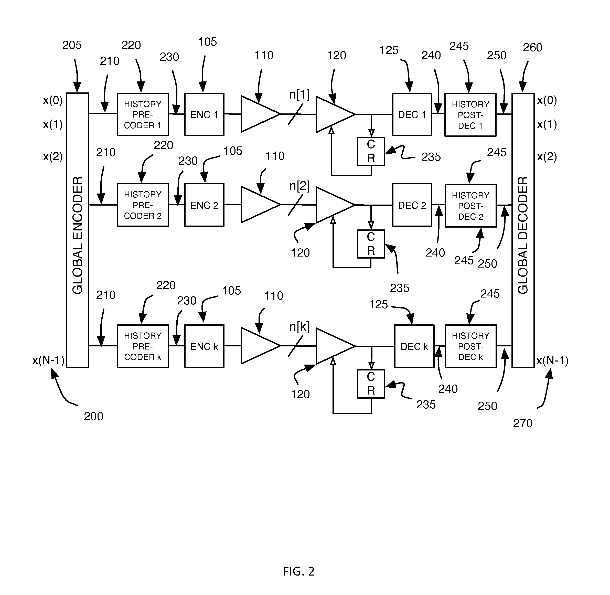
[0124]S3 is a vector signaling code on three wires consisting of the 6 permutations of the vector (+1, 0, −1). In this case, we may choose k=4, corresponding to four communication sub-systems in FIG. 2, and M(1)=M(2)=M(3)=M(4)=6, satisfying the inequality of (Eqn. 3). The resulting embodiment is hereinafter called S34, referring to its four sub-systems, each utilizing S3 vector signaling code. This coding scheme is similar to the one reported in [Wiley], though the details of the encoding and decoding are different.
[0125]An embodiment of the encoder is detailed in FIG. 11. The input to the Global Encoder are the 9 bits x0, x1, . . . , x8 corresponding to an integer between 0 and 256 inclusive. This means that x0=x1= . . . =x7=0 if x8=1. In this communication system there is no Global Encoder unit. Instead, the incoming bits are subdivided into three groups (x0, x1), (x2, x3), (x4, x5) of two bits, and (x6, x7, x8) of three bits. Because of the restriction of the input bits, the f...
example 3
Code S42×P3
[0133]The S4 code is a vector signaling code on four wires consisting of the 12 distinct permutations of the vector (+1, 0, 0, −1). This code can be detected using six pairwise comparators. The ISI ratio of this code is 2.
[0134]The P3 code is a vector signaling code on three wires consisting of the four codewords (1, 0, −1), (−1, 0, 1), (0, 1, −1), and (0, −1, 1). The codewords can be detected using the comparators x−y and (x+y) / 2−z on the received signals (x,y,z) on the three wires. The ISI ratio of this code is 1.
[0135]For the communication system in FIG. 2, we choose 3 communication sub-systems, i.e., k=3, wherein the first two communication sub-systems use the vector signaling code S4, and the third one uses the vector signaling code S3. We have M(1)=M(2)=12, and M(3)=4, so that the inequality of (Eqn. 3) is satisfied. The resulting code is called S43×P3.
[0136]The Global Encoder 205 of FIG. 2, and the Global Decoder 260 of FIG. 2 can operate according to the procedure...
PUM
 Abstract
Description
Claims
Application Information