Cup holder
- Summary
- Abstract
- Description
- Claims
- Application Information
AI Technical Summary
Benefits of technology
Problems solved by technology
Method used
Image
Examples
first embodiment
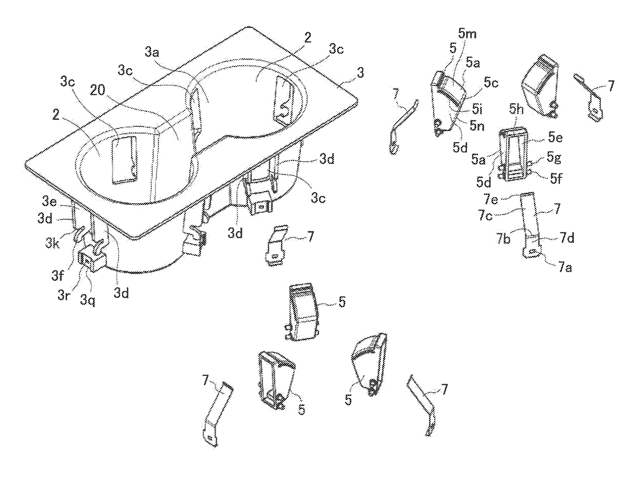
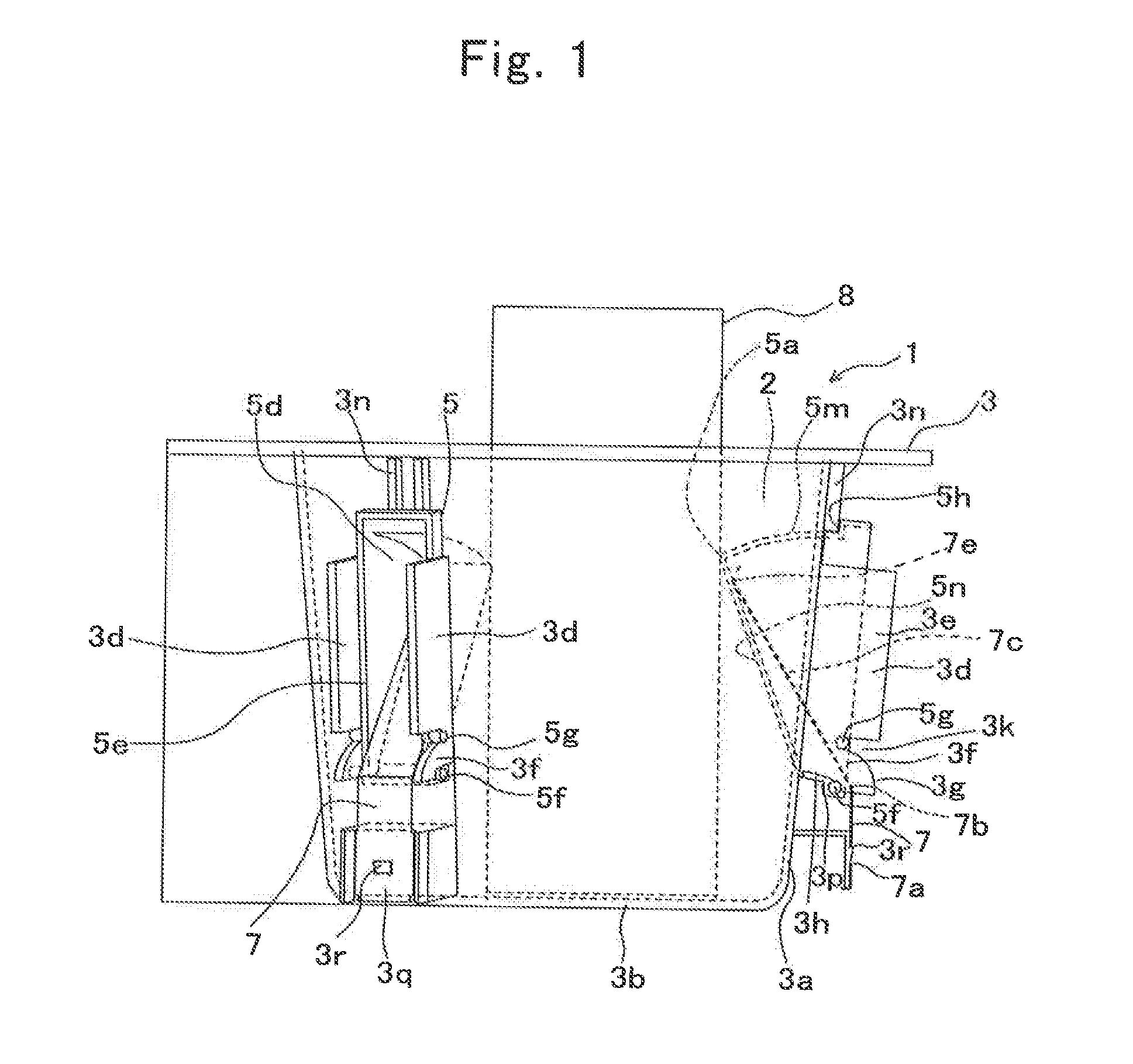
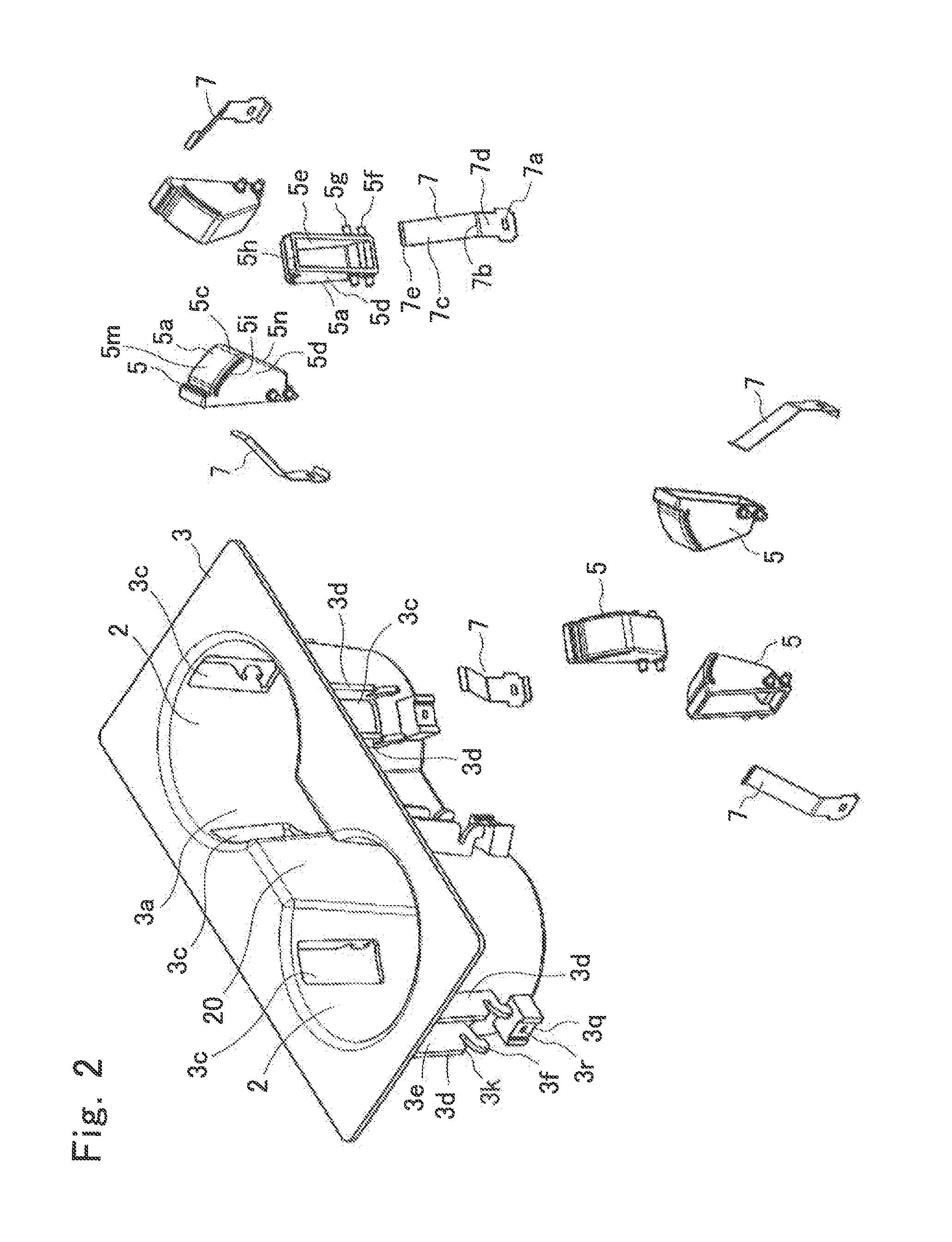
[0032]A cup holder 1 according to the first embodiment of the present invention, as shown in FIGS. 1 and 2, includes a bottomed-cylindrical holder body 3 in which two storage spaces 2 for storing a beverage container 8, a support 5 that advances into or retreats from the storage spaces 2, and a leaf spring 7 (biasing member) biasing the support 5 in a direction in which the support 5 advances into the storage spaces 2.
[0033]The holder body 3 is made of a resin and formed by injection molding. The holder body 3 has a bottomed-cylindrical shape. The holder body 3 has a cylindrical side wall 3a and a bottom wall 3b which closes the lower end of the side wall 3a. A space surrounded by the side wall 3a and the bottom wall 3b is the storage space 2 for storing the beverage container 8. The beverage container 8 is inserted from above the storage spaces 2. The two storage spaces 2 have recessed parts which communicate with each other through a recessed portion 20.
[0034]An inner diameter of ...
second embodiment
[0056]In a cup holder according to a second embodiment, as shown in FIG. 7, the bearing portion 3h formed at the nipped portion 3f of the holder body 3 has an arc-like bearing surface 3s having an arc-like shape having a size almost equal to an outside dimension of the turning shaft 5f, the holding surface 3j holding a surface of the turning shaft 5f on the retreating side, and a contact surface 3u brought into contact with a surface of the turning shaft 5f on the advancing side. The rear side of the arc-like bearing surface 3s is continuously connected to the holding surface 3j, and the advancing side thereof is continuously connected to the contact surface 3u. The holding surface 3j and the contact surface 3u extend downward by several millimeters from the portion being in contact with the turning shaft 5f. Between the lower end of the holding surface 3j and the lower end of the contact surface 3u, the bearing portion guiding portion 3p guiding the turning shaft 5f to the bearing ...
third embodiment
[0058]In a cap holder according to a third embodiment, as shown in FIG. 8, the bearing portion 3h formed on the lower side of the nipped portion 3f of the holder body 3 has a linear bearing surface 3q extending from the side wall 3a to the rear side and the holding surface 3j bent from the rear side of the linear bearing surface 3q and extending downward in the vertical direction. The guide portion 3g formed on the upper side of the nipped portion 3f has a linear guide surface 3r extending from the side wall 3a to the rear side and an arc-like guide surface 3s curved in an arc-like shape from the rear side of the linear guide surface 3r. The linear guide surface 3r of the guide portion 3g is formed in parallel with the linear bearing surface 3q of the bearing portion 3h. A start point of the linear guide surface 3r of the guide portion 3g is located on the side wall 3a, and an end point of the linear guide surface 3r is continuously connected to the start point of the arc-like guide...
PUM
 Abstract
Description
Claims
Application Information
 - R&D
- Intellectual Property
- Life Sciences
- Materials
- Tech Scout
- Unparalleled Data Quality
- Higher Quality Content
- 60% Fewer Hallucinations
Browse by: Latest US Patents, China's latest patents, Technical Efficacy Thesaurus, Application Domain, Technology Topic, Popular Technical Reports.
© 2025 PatSnap. All rights reserved.Legal|Privacy policy|Modern Slavery Act Transparency Statement|Sitemap|About US| Contact US: help@patsnap.com


