Optical assembly

a technology of optical assembly and optical components, applied in the field of optical assembly, can solve the problems of reducing the resolution and overall quality of the projected imag

Active Publication Date: 2015-09-10
GOOGLE LLC
View PDF4 Cites 89 Cited by
  • Summary
  • Abstract
  • Description
  • Claims
  • Application Information

AI Technical Summary

Benefits of technology

[0064]Optionally the optical assembly may further comprise any one or

Problems solved by technology

The induced speckle effect will reduce the resol

Method used


Image

  • Optical assembly
  • Optical assembly
  • Optical assembly

Examples


Embodiment Construction

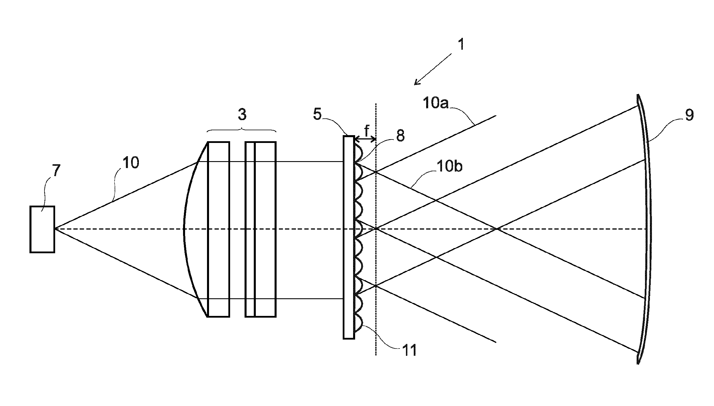
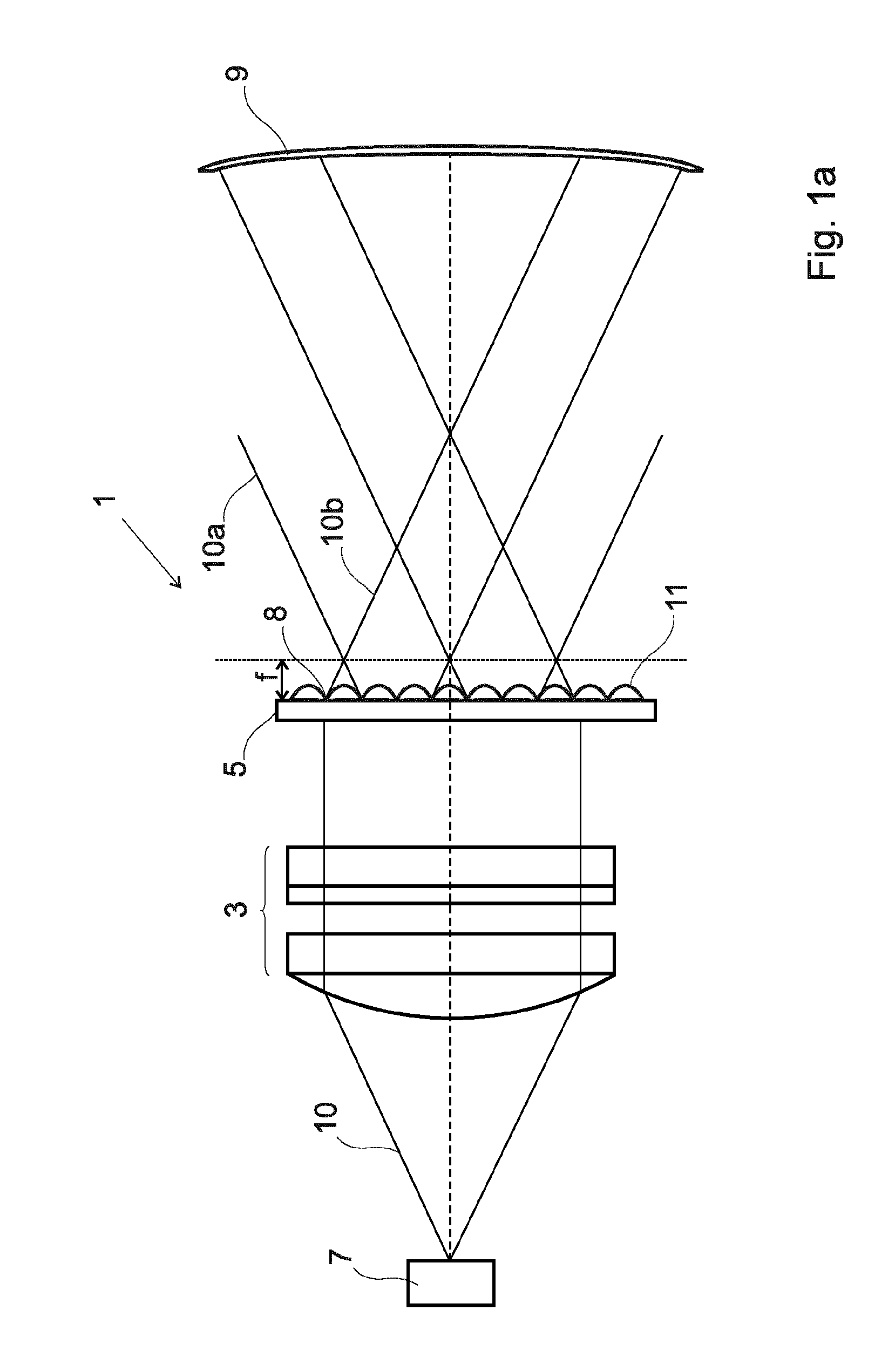
[0082]FIG. 1a shows a side view of an optical assembly 1 according to a first aspect of the present invention. The optical assembly 1 comprises a telecentric lens 3 arranged to be in optical communication with a microlens array 5.

[0083]The optical assembly 1 further comprises a light source 7 which is in optical communication with the telecentric lens 3. It will be understood that the light source 7 in this embodiment and in all other embodiments described herein may comprise a MEMS based projector i.e. a projector which comprises a MEMS micro mirror which oscillates to scan light. The optical assembly further comprises a beam combiner 9 which is arranged such that it can receive light from the microlens array 5.

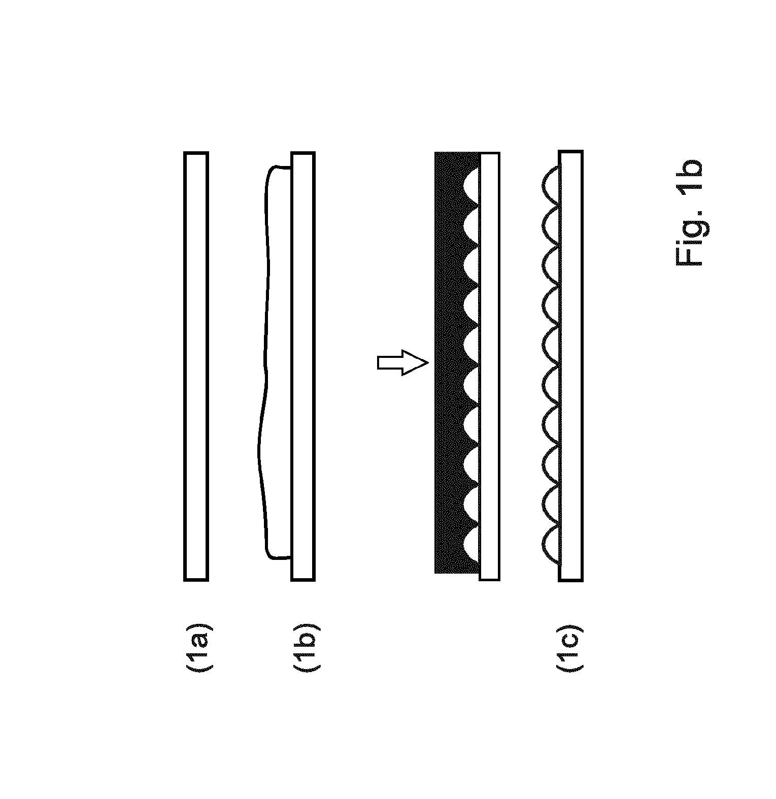
[0084]The microlens array 5 may take any suitable form. Each lens in the array is known as a lenslet 11. The lenslets 11 may take any suitable form; typically, each lenslets 11 may have a hemispherical shape. Alternatively each lenslet 11 may have a semi-cylindrical or a con...


PUM


Abstract

An optical assembly, and in particular an optical assembly which uses a microlens array or a micromirror array to reduce speckle. It further concerns an optical component which comprises a micromirror array.

Description

FIELD OF THE INVENTION[0001]The present invention concerns an optical assembly, and in particular an optical assembly which comprises a microlens array or a micromirror array. It further concerns an optical component which comprises a micromirror array.DESCRIPTION OF RELATED ART[0002]Many projection systems in use today feature light diffusers. The light diffusers are used to diffuse light beams which they received. The diffusion of light beams in a projection system is done so as to create a field of view i.e. a region wherein the projected image can be seen by a viewer. A field of view enables a user to move within the field of view and to still see the image; without a field of view created by the diffuser a user could only see the projected image when they are located at a single location. Diffusers are therefore used in projection systems to provide and define a field of view.[0003]Diffusers are used, for example in HUD (Head-up-displays) so as to enable a virtually projected i...

Claims


Application Information

Patent Timeline
IPC IPC(8): G02B3/00G02B13/22
CPCG02B13/22G02B3/005G02B3/0056G02B5/10G02B27/0101G02B3/0006G02B5/0215G02B2027/0118
Inventor LE GROS, CHRISTOPHEMASSON, JONATHANKILCHER, LUCIO
Owner GOOGLE LLC
Why Eureka
Try Eureka