Microscope with at least one illuminating beam in the form of a light sheet

a technology of light sheet and microscope, which is applied in the field of microscopes, can solve the problems of disadvantageous positioning of specimens in light sheet, time-consuming method for capturing three-dimensional specimens, and inability to achieve the effect of capturing three-dimensional specimens

Inactive Publication Date: 2015-09-10
KARLSRUHER INST FUR TECH
View PDF1 Cites 31 Cited by
  • Summary
  • Abstract
  • Description
  • Claims
  • Application Information

AI Technical Summary

Problems solved by technology

This method is very time-consuming for capturing a three-dimensional specimen, in particular if the signal-to-noise ratio is to be optimised and reaches its limits in the case of a quick time sequence of three-dimensional images of a specimen.
One problem with existing constructions is in particular the positioning of specimens in the light sheet.
This type of positioning is disadvantageous especially for large specimens, for example embryos, because they are each embedded in a matrix, which usually has different optical properties from the specimen itself and from the respective environment, for example air, water or saline solution.
Furthermore, total embedding prevents the growth of biological specimens, for example embryos during time lapse images over several hours, which is particularly disadvantageous for in vivo microscopy of microscopically large specimens.
This is problematic inasmuch as, in optimal double-sided illumination, the same properties are desirable from both illumination sides.
If the slide holding the cells is orientated parallel to the light sheet, more scattered light occurs during illumination and detection near the glass surface, which brings about a poor signal-to-noise ratio.
A further disadvantage of existing devices for light sheet microscopy is the quick and correct positioning of the loose or embedded specimen in the light sheet.
A rapid changeover between two or more specimens, i.e. so-called screening of a plurality of specimens at the same time on the same device, and their correct alignment relative to the light sheet is complex or impossible for various reasons.
The problems arising from the specifications referred to are obstructive in practice in light sheet microscopy, although they can be solved with a great deal of complexity.
Confined spatial conditions result from the arrangement of the lens and the construction of the sample chamber, which lead to removal of the specimen from the fluid and storage outside of the sample chamber becoming necessary during the changeover of a specimen, which entails unwanted influences on a sensitive specimen, which are not acceptable especially over longer periods of time.
A repetitive positioning of a series of specimens, which is accurate to the micron, for time-lapse images together with integrity of the samples cannot be ensured.
Automation for non-repetitive serial imaging of a plurality of specimens or for repetitive serial imaging of a specific number of specimens over a period of time is therefore not possible.
A changeover of a detection lens and / or an illuminating lens is not easy to accomplish in the current prior art and requires, in particular for an automated change, special devices for light sheet microscopy.
The disadvantage with this is that a change of lens is only possible in one axis.
If more than one lens is to be used, these must be arranged in series, which normally causes problems with space.
If all of the lenses are immersion lenses it is necessary to arrange said lenses fully inside the specimen chamber, which is not practical in particular in the case of a plurality of lenses.
Finally, revolving nosepieces, which are standard in light microscopy, cannot presently be used for light sheet microscopy.
A combination and thus a synergy of a light sheet microscope with an existing light microscope are difficult to achieve in contrast to confocal and multiphoton microscopy.
The major disadvantage with this, namely the narrow field of view, is remedied here by a device for so-called Oblique plane microscopy (OPM), in which the focal plane of the image is refocused and recaptured using two additional air lenses, which are arranged at an angle relative to one another, which is not equal to 90°.

Method used


Image

  • Microscope with at least one illuminating beam in the form of a light sheet
  • Microscope with at least one illuminating beam in the form of a light sheet
  • Microscope with at least one illuminating beam in the form of a light sheet

Examples


second embodiment

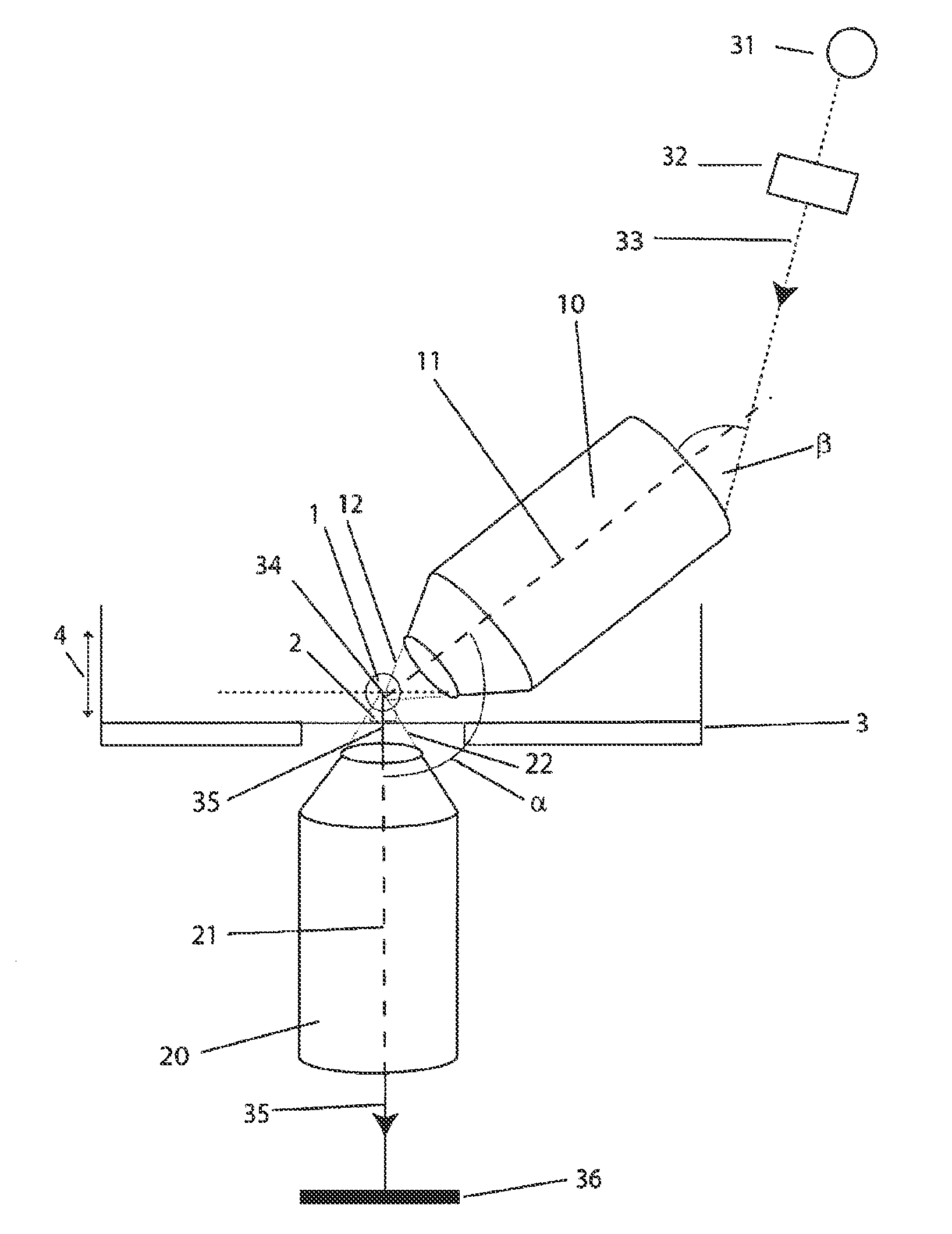
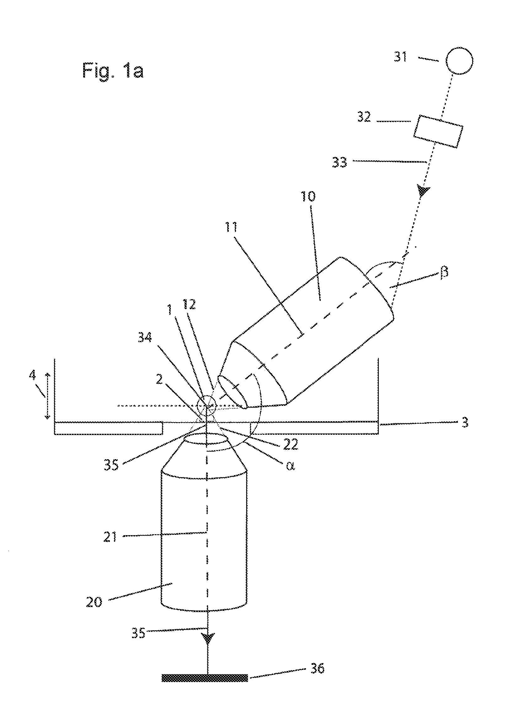
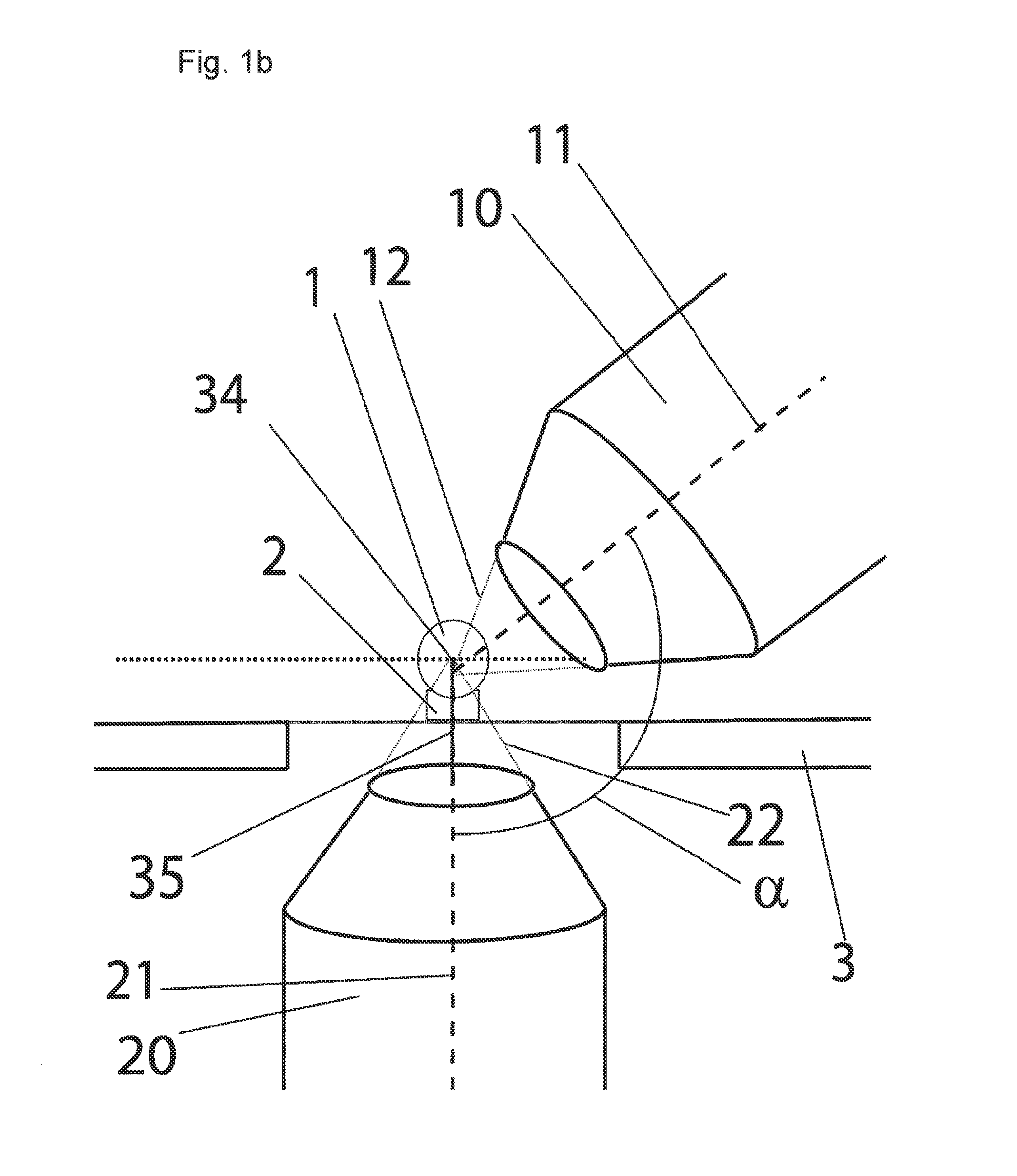
[0044]In the second embodiment shown in FIG. 1c), a light sheet is generated in the second lens, which now acts as an illuminating lens 10, by means of devices known from prior art. Here too, the light sheet does not extend parallel to the optical axis of the illuminating lens 10 as described in the prior art, but rather enters the illuminating lens 10 at a wide entry angle β. This arrangement ensures here, too, that at an angle α of approximately 135° of the optical axes 11, 21 of the lenses 10, 20 relative to one another, the light sheet nevertheless extends perpendicularly to the optical axis 21 of the first lens, which acts here as a detection lens 20. Detection of the detection beam 35, which issues from the specimen 1 and passes through the detection lens 20 along the optical axis 21 thereof is also performed here by means of a detector 36.

third embodiment

[0045] shown in Fig. le), a light sheet is generated in the first lens, which acts as an illuminating lens 10, which light sheet here too does not extend parallel to the optical axis of the illuminating lens 10, but rather enters the illuminating lens 10 at a wide entry angle β and outside the optical 11 axis thereof. As a result of this, even at an angle α of approximately 135° of the optical axes 11, 21 of the lenses 10, 20 relative to one another, the light sheet extends perpendicularly to the optical axis 21 and within the focal plane of the second lens, which acts as a first detective lens 20. The first detection beam 35 issuing from the specimen 1 passes through the first detection lens 20 along the optical axis 21 thereof and is guided onto a detector 36 by means of a first deflection mirror 37. At the same time, a second detection beam 35′ issuing from the specimen 1 is guided through the first lens, which acts as a second detection lens 20′ for this purpose, along the optic...


PUM


Abstract

A microscope includes at least one illuminating lens configured to guide at least one illuminating beam in the form of a light sheet for illuminating at least one specimen to be examined. The microscope also includes at least one detection lens configured to capture at least one detection beam issuing from the at least one specimen to be examined. The at least one illuminating lens has an optical axis at an angle α, which is not equal to 90°, to an optical axis of the at least one detection lens. The at least one illuminating beam enters the at least one illuminating lens at an entry angle β such that the light sheet lies within a focal plane of the at least one detection lens.

Description

CROSS REFERENCE TO RELATED APPLICATIONS[0001]This application is a U.S. National Phase application under 35 U.S.C. §371 of International Application No. PCT / EP2013 / 002647 (WO 2014 / 063764 A1), filed on Sep. 4, 2013, and claims benefit to German Patent Application No. DE 10 2012 110 077.2, filed Oct. 23, 2012.FIELD[0002]The invention relates to microscopes, and in particular to microscopes having at least one illuminating beam having a specimen illumination region (light sheet) expanded transversely to the axis of the illuminating beam for illuminating a three-dimensional specimen to be examined.BACKGROUND[0003]Using existing, conventional, confocal microscopy, a three-dimensional specimen is scanned point by point in two-dimensional optical planes. This method is very time-consuming for capturing a three-dimensional specimen, in particular if the signal-to-noise ratio is to be optimised and reaches its limits in the case of a quick time sequence of three-dimensional images of a speci...

Claims


Application Information

Patent Timeline
Patent Type & Authority Applications(United States)
IPC IPC(8): G02B21/08G02B21/34G02B21/36
CPCG02B21/08G02B21/34G02B21/361G02B21/0032G02B21/0076G02B21/24G02B21/367
Inventor OTTE, JENS CHRISTOPHERSTRAEHLE, UWEKOBITSKI, ANDREINIENHAUS, GERD ULRICH
Owner KARLSRUHER INST FUR TECH
Why Eureka
Try Eureka