Proximity wireless communication device

a wireless communication and wireless communication technology, applied in the direction of ferromagnetic core loop antennas, antenna supports/mountings, transmission, etc., can solve the problems of increasing the cost of the entire system, increasing the size of the housing, etc., to reduce the influence of electromagnetic fields, eliminate or reduce ferrite materials, and facilitate the positioning of antennas

Active Publication Date: 2015-09-10
PANASONIC INTELLECTUAL PROPERTY CORP OF AMERICA
View PDF9 Cites 11 Cited by
  • Summary
  • Abstract
  • Description
  • Claims
  • Application Information

AI Technical Summary

Benefits of technology

[0007]One non-limiting and exemplary embodiment provides a proximity wireless communication device that is, in communication between communication blocks to carry out a plurality of communication sessions in parallel, capable of reducing influence of electromagnetic field generated by one communication session to electromagnetic field of the other communication session and capable of preferred wireless communication.
[0009]According to the configuration as described above, it is possible to reduce influence of electromagnetic field formed by one pair of antennas to electromagnetic field formed by the other pair of antennas and it is possible to perform preferred wireless communication. Since it is possible to eliminate or reduce a ferrite material, the entire device does not increase in size. Further, it is also possible to easily carry out positioning of antennas by a structure of fitting convexity and concavity and thus it contributes to improvement in communication accuracy.

Problems solved by technology

However, with such configuration, problems, such as an increase in costs for the entire system because ferrite is used and an increase in housing size due to an installation space required to provide them, occur.

Method used


Image

  • Proximity wireless communication device
  • Proximity wireless communication device
  • Proximity wireless communication device

Examples


first embodiment

Configuration

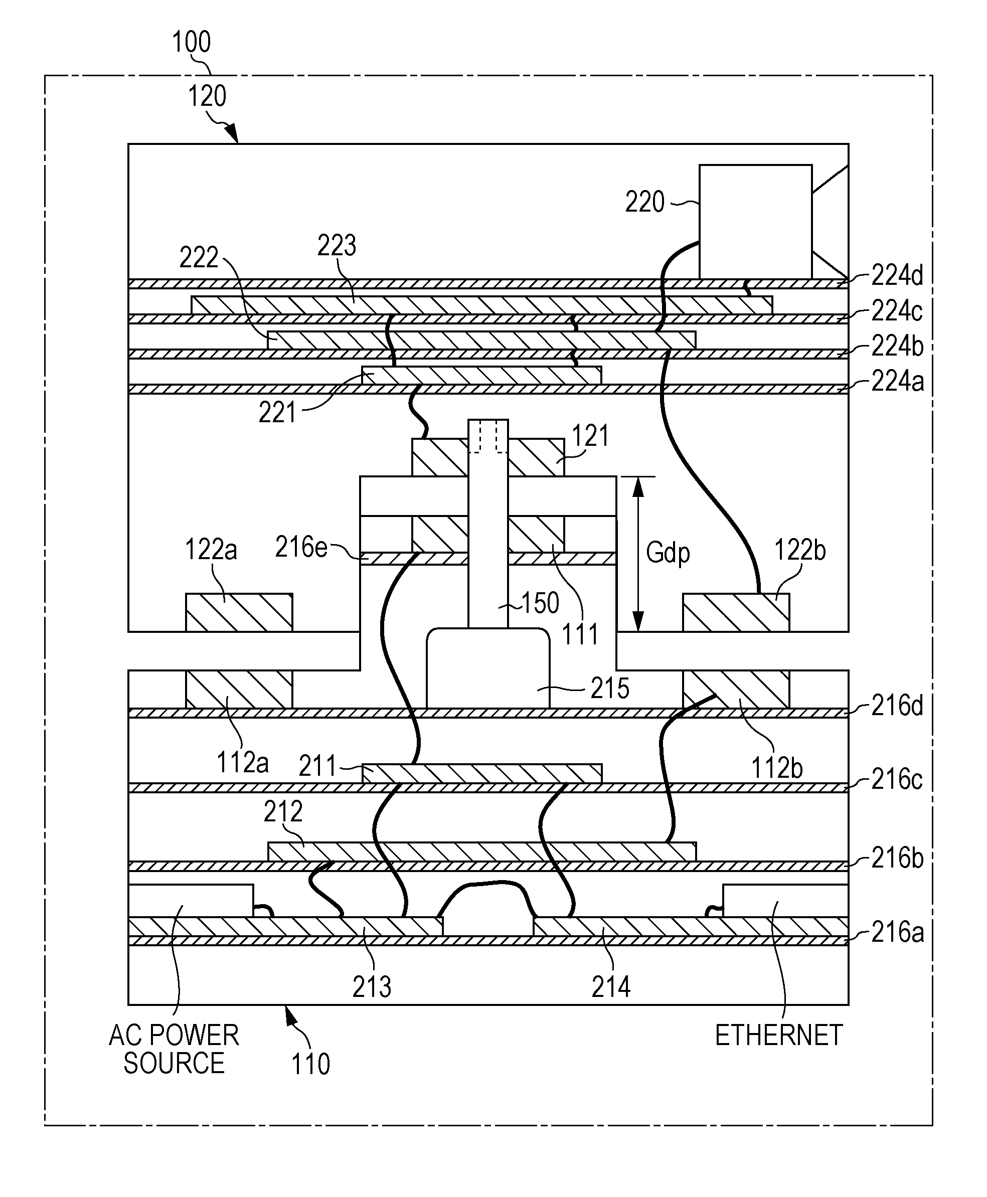
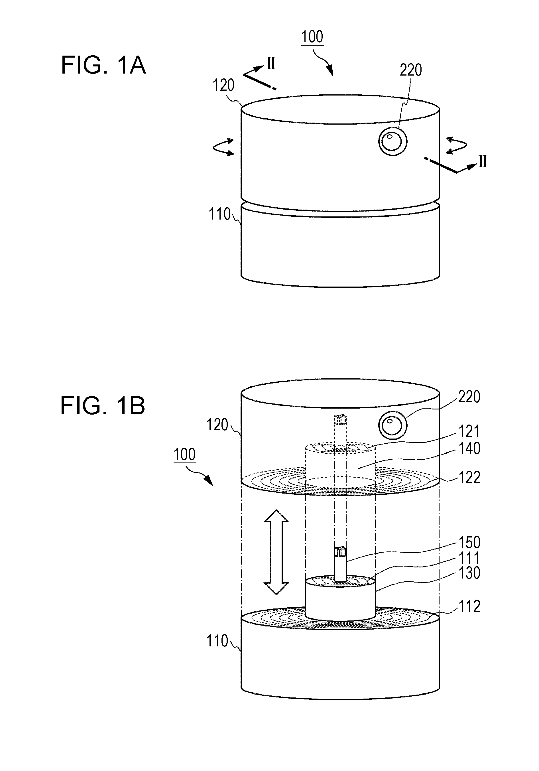
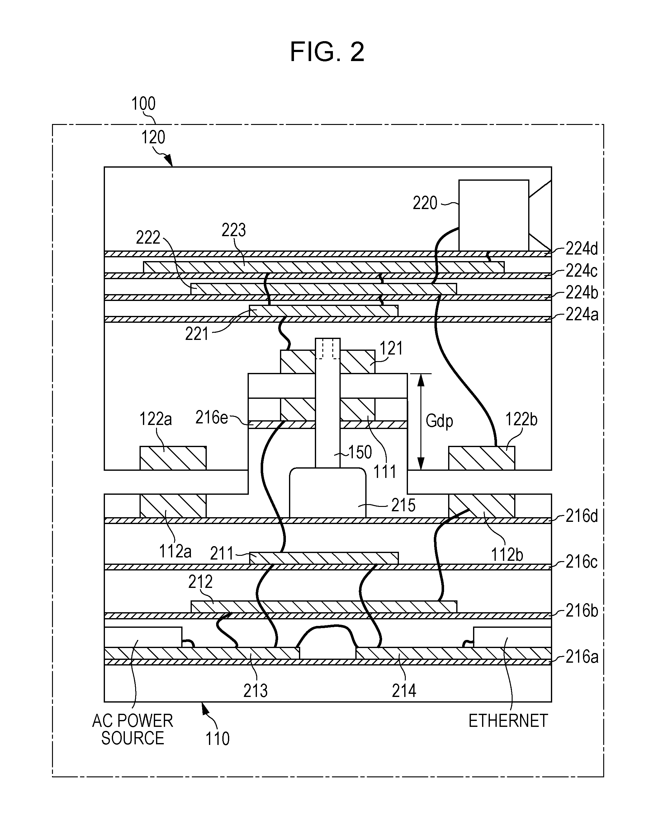
[0036]FIG. 1A is an external view of a proximity wireless communication device 100. FIG. 1B is an exploded perspective view of the proximity wireless communication device 100.

[0037]As illustrated in FIGS. 1A and 1B, the proximity wireless communication device 100 is provided with a first housing 110 and a second housing 120, and a column projection 130 of the first housing 110 and a column recess 140 of the second housing 120 fit. The second housing 120 is provided with a camera 220. It is possible to use the proximity wireless communication device 100 as a surveillance camera and the like by, for example, fixing a bottom surface of the first housing 110 to a ceiling of the facility and the like.

[0038]Although not shown in FIGS. 1A and 1B, a rotation shaft 150 of the first housing 110 is connected to a motor inside the first housing 110. The rotation shaft 150 fits and is adhered to the second housing 120. As the rotation shaft 150 rotates by driving the motor, the seco...

second embodiment

[0077]In the present second embodiment, descriptions are given to a configuration that is capable of enhancing communication accuracy even more than the first embodiment.

[0078]While, in the first embodiment above, the communication accuracy of the communication antenna is enhanced by disposing the communication antenna and the feed antenna on planes different from each other, a configuration is described that is capable of suppressing influence of the non-contact communication between the communication antennas and between the feed antenna and the power receiving antenna to each other and enhancing communication accuracy by further efforts in addition to such configuration.

[0079]Specifically, a magnetic material is equipped at least between the communication antenna and the feed antenna. Although it is described to be possible to suppress degradation of communication even without providing a ferrite material in the first embodiment, a magnetic material may also be equipped as descri...

third embodiment

[0091]In the first and second embodiments above, configuration examples where two pairs of antennas (a pair of communication antennas and a pair of feed and power receiving antennas) are provided are described. However, the pairs of antennas to be provided in the proximity wireless communication device do not have to be limited to two pairs.

[0092]In the present third embodiment, a configuration example where a proximity wireless communication device is provided with three pairs of antennas is described.

[0093]FIG. 8 is a conceptual diagram illustrating an arrangement example of antenna arrangement in a proximity wireless communication device 800 according to the third embodiment, and FIG. 9 is a functional configuration diagram of the proximity wireless communication device 800.

[0094]Although the basic structure is similar to the proximity wireless communication device 100 described in the first embodiment, it is different in being provided with two types of communication antennas of...


PUM


Abstract

A proximity wireless communication device includes a first housing and a second housing, and they are provided with respective two antennas. In the first housing, a first antenna and a second antenna are configured to be disposed on different parallel planes, and in the second housing, a third antenna and a fourth antenna are configured to be disposed on different parallel planes. Then, the first antenna and the third antenna carry out non-contact near-field wireless communication facing in proximity and the second antenna and the fourth antenna carry out non-contact near-field wireless communication facing in proximity.

Description

BACKGROUND[0001]1. Technical Field[0002]The present disclosure relates to a proximity wireless communication device that performs a plurality of communication sessions using a plurality of antennas.[0003]2. Description of the Related Art[0004]In recent years, for designing a device configured with two blocks, when data communication between both blocks is required, non-contact near-field wireless communication utilizing electromagnetic field coupling is sometimes used for the purpose of simplification of device design and cost reduction.[0005]Japanese Unexamined Patent Application Publication No. 2008-301183 discloses a camera device. This camera device is configured with a mounting unit and a rotation unit capable of revolving relative to the mounting unit, and the rotation unit is equipped with a camera. This camera device is provided with a first coil of the mounting unit and a second coil of the rotation unit that are arranged facing each other. This enables power supply and exc...

Claims


Application Information

Patent Timeline
Patent Type & Authority Applications(United States)
IPC IPC(8): H01Q21/00H01Q7/06H01Q1/24
CPCH01Q21/00H01Q7/06H01Q1/24H04B5/0031H04B5/0037H04B5/0075H04B5/0087
Inventor ASAI, KOJINAKAYAMA, TAKESHIKANNO, HIROSHI
Owner PANASONIC INTELLECTUAL PROPERTY CORP OF AMERICA
Why Eureka
Try Eureka