Concealed slide module

a slide module and concealed technology, applied in drawers, furniture parts, domestic applications, etc., can solve the problems of easy vibration and noise, high difficulty in manufacture, and high manufacturing cost, and achieve the effect of preventing vibration or noise easily and minimizing the gap produced

Active Publication Date: 2015-09-17
SUN CHAIN TRADING
View PDF10 Cites 11 Cited by
  • Summary
  • Abstract
  • Description
  • Claims
  • Application Information

AI Technical Summary

Benefits of technology

[0015]In a preferred embodiment, the guide wheel has a protruding length equal to the distance between the middle plate and the outer plate, and the guide wheel has a diameter equal to the distance between the axis of the guide wheel and the anti-loose portion. In addition, the bottom side of the roof portion is in a cambered shape corresponsive to the second ball and disposed opposite to the anti-loose portion for clamping the second ball therebetween. The outer sidewall of the bottom of the guide wheel has a section deviated to the outside, so that the first rollers are coupled to surfaces of the middle plate and the connecting section respectively. The invention can minimize the gap produced after the assembling process to prevent producing vibrations or noises easily when the concealed slide module performs an extending or contracting movement.

Problems solved by technology

However, the drawers may produce vibrations and noises in practical applications.
It is noteworthy that dimensions and symmetrical positions must be taken into consideration for manufacture the drawer slide with of the design of the dual roof portions 11, and thus having a very high level of difficulty of the manufacture and incurring a high manufacturing cost.
On the other hand, the dual wheel design comes with a too-large gap, and thus causing vibrations and noises easily.

Method used


Image

  • Concealed slide module
  • Concealed slide module
  • Concealed slide module

Examples


Embodiment Construction

[0021]The technical content of the present invention will become apparent with the detailed description of preferred embodiments and the illustration of related drawings as follows.

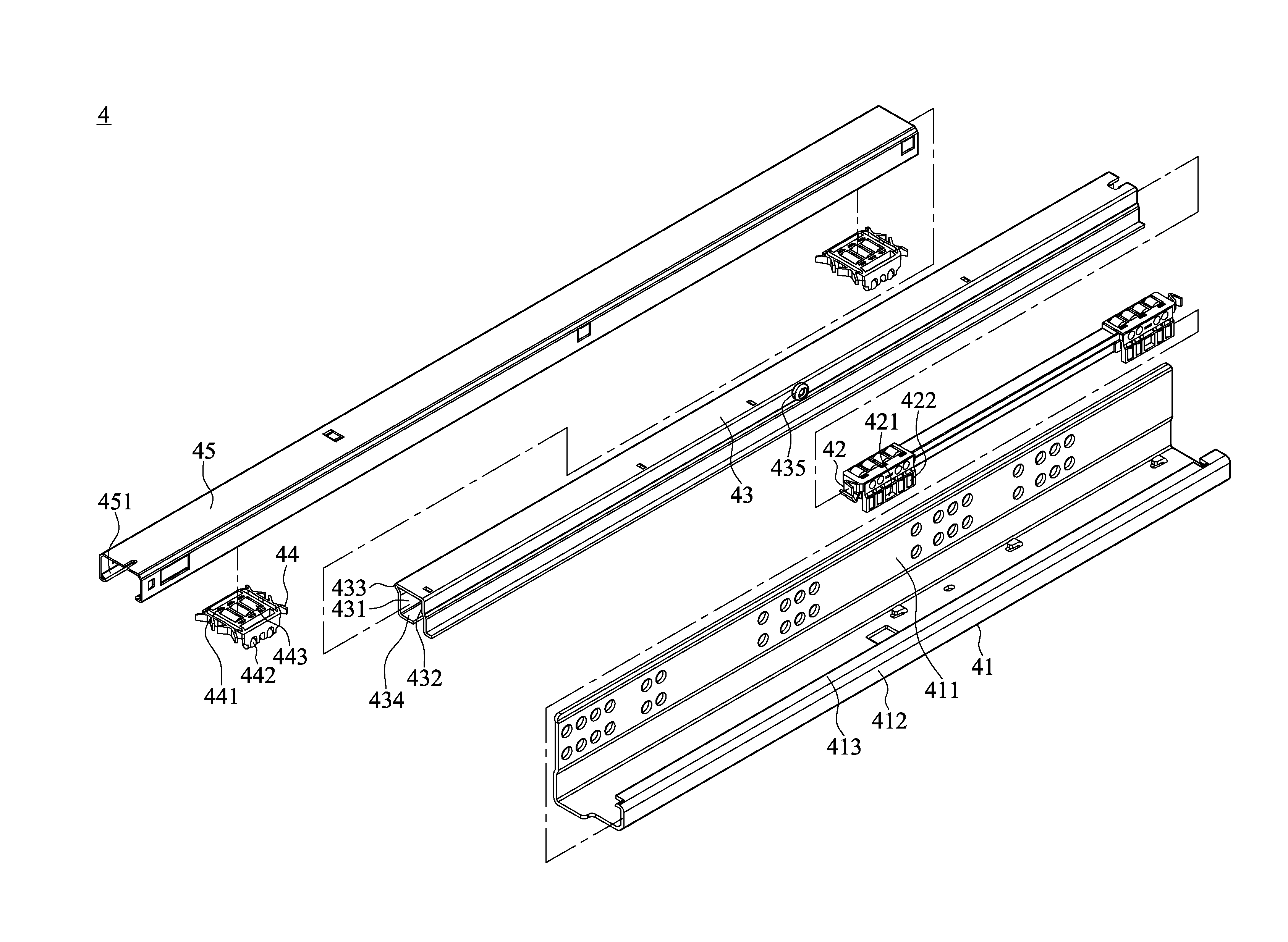
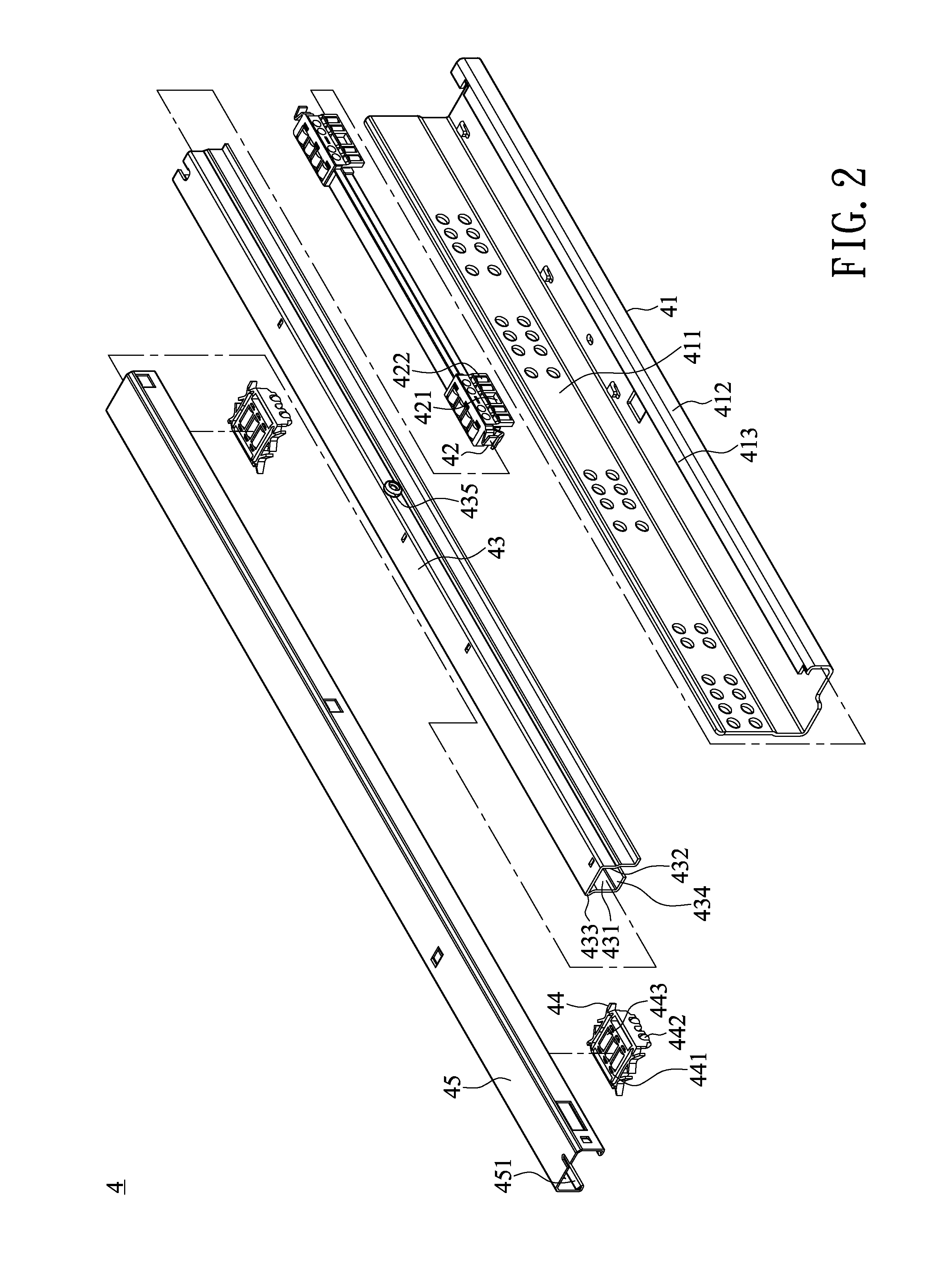
[0022]With reference to FIGS. 2 to 4 for an exploded view, a cross-sectional view and a schematic view of a using status of a concealed slide module in accordance with a preferred embodiment of the present invention respectively, the concealed slide module 4 comprises an inner plate 41, a pair of first ball plates 42, a middle plate43, a pairs of second ball plates 44 and an outer plate 45, installed between a bottom side of a drawer 5 and a cupboard 6.

[0023]Wherein, the inner plate 41 is a structure made of a metal sheet and bent into the structure with a substantially L-shaped cross-section, and a side of the inner plate has a folded plate 411 provided for installing to an inner side of the cupboard 6, and the inner plate 41 has a connecting section 412 bent perpendicularly upward from the other edge of...


PUM


Abstract

A concealed slide module is formed by installing an inner plate, at least one first ball plate, a middle plate, at least one second ball plate and an outer plate sequentially and installed between a bottom side of a drawer and a cupboard. The middle plate covers the exterior of the first ball plate and has an inner sidewall facing the inner plate and having a roof portion protruded horizontally outward from the top side of the middle plate, and a sliding section bent inwardly from a lower edge of the sidewall, and the sliding section is parallel to the platform, and a guide wheel is protruded from an outer sidewall at an end of the middle plate, and the middle plate slides with respect to the inner plate through the first ball plate.

Description

CROSS-REFERENCE TO RELATED APPLICATIONS[0001]This non-provisional application claims priority under 35 U.S.C. §119(a) on Patent Application No(s). 103204394 filed in Taiwan, R.O.C. on Mar. 14, 2014, the entire contents of which are hereby incorporated by reference.BACKGROUND OF THE INVENTION[0002]1. Field of the Invention[0003]The present invention relates to the technical area of downwardly mounted slides for drawers, and more particularly to a concealed slide module with the design of a middle plate and having a roof portion and a guide wheel on two sidewalls to improve the stability and reliability.[0004]2. Description of the Related Art[0005]In general, a piece of furniture having a drawer such as a file cabinet, a cupboard and a desk usually comes with a pair of slides connected between the drawer and the furniture to facilitate users to push / pull the drawer to shut or open the drawer, and the slides are provided for carrying the load of the drawer and sliding the drawer. The c...

Claims


Application Information

Patent Timeline
Patent Type & Authority Applications(United States)
IPC IPC(8): A47B88/04A47B88/493
CPCA47B88/0466A47B88/04A47B2210/004A47B88/493A47B88/437A47B88/40
Inventor CHEN, BI-SHA
Owner SUN CHAIN TRADING
Why Eureka
Try Eureka