Endoscope

Active Publication Date: 2015-09-17
OLYMPUS CORP
View PDF16 Cites 8 Cited by
  • Summary
  • Abstract
  • Description
  • Claims
  • Application Information

AI Technical Summary

Benefits of technology

[0010]The endoscope disclosed in PTL 2 ensures light distribution by providing a large distance between the observation optical system and the illumination optical systems, resulting in an increase in diameter of a distal end of the endoscope.
[0011]The present

Problems solved by technology

Therefore, when a subject to be focused on is positioned at the center part, a favorable o

Method used


Image

  • Endoscope
  • Endoscope
  • Endoscope

Examples


example 1

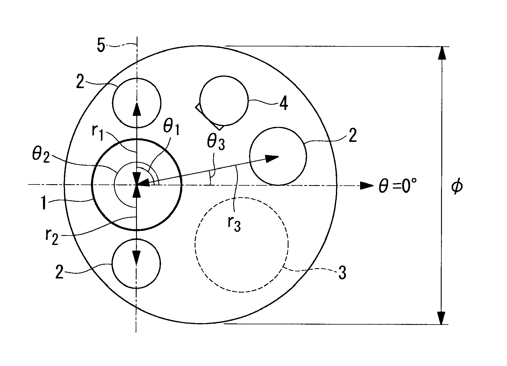
[0090]A front view of a distal end of an insertion portion of an endoscope according to Example 1 of the present invention is illustrated in FIG. 6. In Example 1, a total of three illumination optical systems, which are two identical illumination optical systems 2a and an illumination optical system 2b, are employed.

[0091]In the present example, r1=3.2, r2=3.2, r3=5.16, θ1=90°, θ2=270°, θ3=8.9° and φ=9.9.

[0092]FIG. 7 illustrates a lens configuration of an observation optical system 1 employed in the endoscope according to the present example, and FIG. 8 illustrates a lens configuration of the illumination optical systems 2a and 2b employed in the endoscope according to the present example.

[0093]Lens data of the observation optical system according to Example 1 of the present invention are indicated below.

Lens Data

[0094]

SurfacenumberrdNdVdObjectsurface∞d0 1∞0.401.88340.7621.110.633∞0.401.52165.134∞0.305−4.491.561.51752.436−2.210.067∞0.971.75035.338−1.560.361.92318.99−2.700.0310(Diaph...

example 2

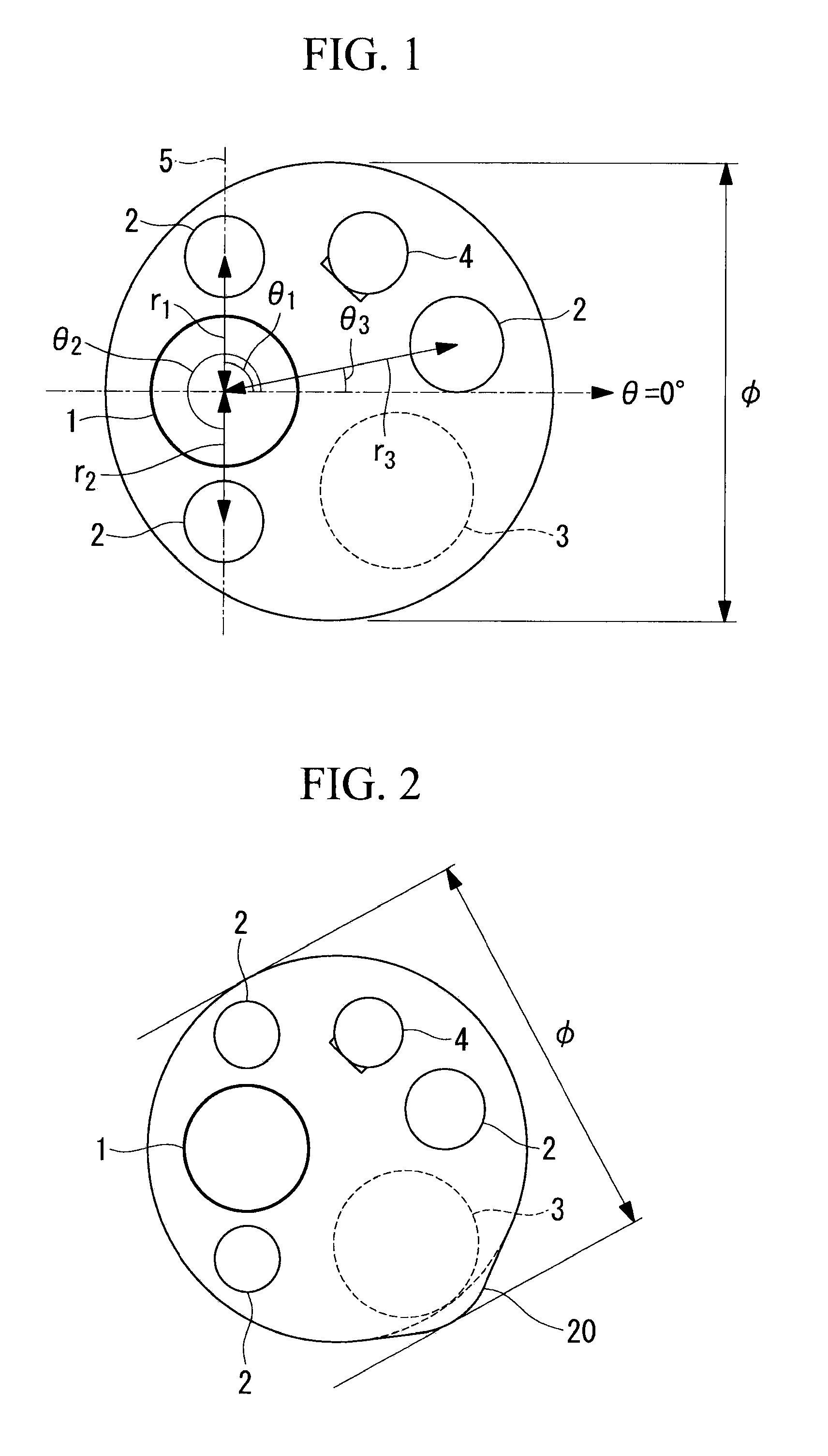
[0104]A front view of a distal end of an insertion portion of an endoscope according to Example 2 of the present invention is illustrated in FIG. 9. Also, FIG. 10 illustrates a lens configuration of an observation optical system 1 employed in the endoscope according to the present example.

[0105]In the present example, r1=3.99, r2=3.84, r3=3.80, θ1=28.2°, θ2=157.9°, θ3=294.6° and φ=13.2.

[0106]Lens data of the observation optical system according to Example 2 of the present invention are indicated below.

Lens Data

[0107]

SurfacenumberrdNdVdObjectsurface∞d0 1∞0.481.88340.7621.390.803∞0.401.52165.134∞0.425−2.221.411.75035.336−2.540.0374.561.071.77349.68−2.420.371.92318.99−4.670.2910(Diaphragm)∞d1011∞0.401.48870.23121.630.401.59335.31132.10d13144.511.331.48870.2315−3.300.05166.341.921.48870.2317−2.190.481.92318.918−6.590.0319∞0.401.52358.520∞0.6321∞0.901.51664.1422∞0.601.50563.2623(Imageplane)∞

Various Data

[0108]

NormalobservationMaximummagnificationd0502.2d100.291.7d131.870.46Focallength1.49...

example 3

[0112]A front view of a distal end of an insertion portion of an endoscope according to Example 3 of the present invention is illustrated in FIG. 11. Also, FIG. 12 illustrates a lens configuration of an observation optical system 1 employed in the endoscope according to the present example.

[0113]In the present example, r1=3.47, r2=3.68, r3=3.47, θ1=28.4°, θ2=155.3°, θ3=303.9° and T=11.7.

[0114]Lens data of an observation optical system according to Example 3 of the present invention are indicated below.

Lens Data

[0115]

SurfacenumberrdNdVdObjectsurface∞d0 1∞0.361.88340.7621.190.753∞0.401.52165.134∞0.375−3.551.781.58140.756−2.380.3076.830.831.51752.438−1.380.301.92318.99−2.140.0510(Diaphragm)∞d1011∞0.311.77349.6121.420.581.72829.46133.67d13144.681.201.81646.6215−6.020.03164.911.601.61863.3317−2.420.361.92318.91811.20.1619∞0.401.52358.520∞0.8321∞0.801.51664.1422∞0.701.50563.2623(Imageplane)∞

Various Data

[0116]

NormalobservationMaximummagnificationd0502.5d100.321.78d131.90.44Focallength1.191...


PUM


Abstract

An endoscope includes an observation optical system that allows a magnified observation close to a subject, and illumination optical systems. In a close observation, ITM is a maximum brightness within an observation view field angle, and ITC is a center brightness. In a normal observation IWC is a center brightness, and IWS is a brightness at a position of 80% of a maximum view angle. The following is satisfied:
0.3<ITC/ITM<0.45
0.15<IWS/IWC<0.25
0.3<fLfTLIH<0.6
where fL is a focal length of each of the entire illumination optical systems, fT is a focal length of the entire observation optical system in a maximum magnification, φL is an outer diameter of a lens that is farthest on an object side of each illumination optical system, and IH is a maximum image height of the observation optical system.

Description

CROSS-REFERENCE TO RELATED APPLICATIONS[0001]This application is a Continuation Application of International Application PCT / JP2014 / 063513 filed on May 21, 2014, which claims priority to Japanese Application No. 2013-108141 filed on May 22, 2013.[0002]The Contents of International Application PCT / JP2014 / 063513 and Japanese application No. 2013-108141 are hereby incorporated by reference herein in its entirety.TECHNICAL FIELD[0003]The present invention relates to an endoscope including illumination optical systems and an observation optical system.BACKGROUND ART[0004]Typically, in a distal end portion of an endoscope, structural objects such as an illumination optical system for illuminating a subject, an observation optical system including, at a distal end face thereof, an optical member for receiving incoming light from the subject, a channel that guides a treatment instrument, and a nozzle for cleaning dirt adhering to a lens surface of the image pickup optical system are provide...

Claims


Application Information

Patent Timeline
IPC IPC(8): A61B1/00A61B1/05A61B1/06
CPCA61B1/00096A61B1/05A61B1/0676A61B1/00G02B23/2423G02B23/243G02B23/26A61B1/00188A61B1/07
Inventor SONE, NOBUHIKOTAKATO, HIDEYASU
Owner OLYMPUS CORP
Why Eureka
Try Eureka