Magnetically connected medical tubing

Pending Publication Date: 2020-03-19
UNIVERSITY OF ROCHESTER
View PDF4 Cites 1 Cited by
  • Summary
  • Abstract
  • Description
  • Claims
  • Application Information

AI Technical Summary

Benefits of technology

[0009]The invention provides systems, devices, and methods for magnetically connected medical tubing. In some embodiments, the invention provides medical tubing system with sections releasably held together by magnetic attraction, comprising (a) a first section of medical grade elastomeric tubing having a length, an exterior, a proximal end and an opposing distal end having a diameter, a first opening at the proximal end and a second opening at the distal end, a first lumen fluidly connected to the first opening, the lumen having a diameter and extending through the first section and fluidly connecting the first opening to the second opening of the first section, (b) a second section of medical grade elastomeric tubing having a length, a proximal end having a first diameter matching the diameter of the distal end of the first section, an exterior, a proximal end having a first opening and a distal end having a second opening, which distal end further optionally (i) has a second diameter greater than the diameter, or (ii) is adapted to expand in diameter from that of the first diameter to a larger diameter, a first lumen of the second section, the first lumen of the second section having a diameter extending through the second section and fluidly connecting the first opening to the second opening of the second section, and (c) the first and the second sections are releasably held together by a selected magnetic force between (i) at least one magnet disposed on the exterior of the distal end of the first section and at least one magnet disposed on the exterior of the proximal end of the second section, the at least one magnet on the first and second sections positioned to releasably hold the second opening of the first section and the first opening of the second section together with a first selected magnetic force, (ii) at least one magnet disposed on the exterior of the distal end of the first section and a ferromagnetic material disposed on the exterior of the proximal end of the second section, the at least one magnet and the ferromagnetic material positioned to releasably hold second opening of the first section and the first opening of the second section of tubing together with a first selected magnetic force, or (iii) a ferromagnetic material disposed on the exterior of the distal end of the first section and at least one magnet disposed on the exterior of the proximal end of the second section, the ferromagnetic material and the at least one magnet positioned to releasably hold the second opening of the first section and the first opening of the second section together with a first selected magnetic force. In some embodiments, one or more additional magnets are disposed around the exterior of the distal end of the first section, around the exterior of the proximal end of the second section, or both. In some embodiments, (i) the at least one magnet of element (c)(i) disposed on the distal end of the first section is configured as a ring or a cylinder around the exterior of the distal end of the first section and is attached to the exterior, and the at least one magnet of element (c)(i) disposed on the proximal end of the second section of element (c)(i) is configured as a ring or cylinder around the proximal end of the second section and is attached to the exterior, (ii) the at least one magnet of element (c)(ii) is configured as a ring or cylinder around the exterior of the distal end of the first section and is attached to the exterior, and the ferromagnetic material magnet of element (c)(i) is configured as a ring or cylinder around the exterior of the proximal end of the second section and is attached to the exterior, or (iii) the ferromagnetic material of element (c)(iii) is configured as a ring or cylinder around the exterior of the distal end of the first section and is attached to the exterior, and the at least one magnet of element (c)(iii) is configured as a ring or cylinder around the exterior of the proximal end of the second section and is attached to the exterior. In some embodiments, the attachment of the magnets and the ferromagnetic material is by a medical grade adhesive. In some embodiments, the one least one magnet on the first section or on the second section, or both, and the ferromagnetic material, is covered with, or embedded in, a medical grade elastomeric material. In some embodiments, the distal end of the first section terminates into a nozzle fitting into the first lumen of the second section. In some embodiments, the nozzle is cylindrical. In some embodiments, the nozzle has a taper. In some embodiments, the proximal end of the second section contains a one-way valve, which valve is held open when the nozzle of the first section is present and which is in closed position when the nozzle is not present. In some embodiments, the distal end of the second section has a diameter expanded from that of the first diameter of the second section or has an adaption to increase in diameter when desired. In some embodiments, the adaption to increase in diameter when desired is an inflatable balloon. In some embodiments, the first and the second sections comprise a second lumen extending therethrough fluidly connecting an inflation port at the proximal end of the first section with the inflatable balloon on the distal section of the second section. In some embodiments, the adaption to increase in diameter when desired is an expandable bolster. In some embodiments, the expanded diameter of the distal end of the second section is created by two or more wings extending from the distal end. In some embodiments, the expanded diameter of the distal end of the second section is a rim or lip of material with a diameter larger than that of the second section. In some embodiments, the expanded diameter of the distal end of the second section is an expanded tip. In some embodiments, the expanded diameter of the distal end of the second section is bulbous. In some embodiments, the expanded diameter of the distal end of the second section is a hemispherical dome having a wide bottom, which wide bottom is disposed facing towards the first section of the medical tubing. In some embodiments, the first section is longer than the second section. In some embodiments, the second section has an external retention ring positioned between the connection of the first and second sections and the distal end of the second section. In some embodiments, the medical tubing is a gastrostomy (“G”) tube, a jejunostomy (“J”) tube, or a G-J tube. In some embodiments, the distal end of the medical tubing is adapted to mate to a low-profile button, with the lumen of the medical tubing system fluidly connected to a lumen in the low-profile button and further fluidly connecting to a tube extending distally from the low-profile button. In some embodiments, the medical tubing is a G tube, a J tube, or a G-J tube. In some embodiments, the medical tubing is a drainage catheter. In some embodiments, the catheter is a Foley catheter. In some embodiments, the medical tubing is a chest tube. In some embodiments, the medical tubing is an intravenous line. In some embodiments, the intravenous line is a central line or an arterial line. In some embodiments, the medical tubing is an endotracheal tube. In some embodiments, the preselected magnetic force is between 2 pounds and about 30 pounds. In some embodiments, the preselected magnetic force is between 5 pounds and about 20 pounds. In some embodiments, the preselected magnetic force is between 8 pounds and about 15 pounds. In some embodiments, the preselected magnetic force is between about 8 pounds and about 12 pounds. In some embodiments, the preselected magnetic force is about 30 pounds. In some embodiments, the magnet, the ferromagnetic material, or both, are removable. In some embodiments, the distal end of the first section and the proximal end of the second section are configured to reversibly hold the magnets of element (i) or the magnets and ferromagnetic materials of elements (ii) or (iii), respectively. In some embodiments, the configuration of the ends is by (i) providing the distal end of the first section with male or female helical ridges and providing a magnet or a ferromagnetic material, or a holder holding the magnet or the ferromagnetic material with helical ridges mating to the helical ridges of the distal end of the first section, and (ii) providing the proximal end of the second section with male or female helical ridges and providing a magnet or a ferromagnetic material, or a holder holding the magnet or the ferromagnetic material with helical ridges mating to the helical ridges of the proximal end of the second section.
[0010]In another group of embodiments, the invention provides medical tubing systems with a low-profile button, comprising (a) a first section of medical grade elastomeric tubing having a length, a diameter, an exterior, a proximal end and an opposing distal end, a first opening port at the proximal end, a first lumen fluidly connected to the first opening port, the lumen having a diameter, and extending through the length of the first section from the first opening to a second opening in the distal end of the first section, (b) a low-profile gastrostomy button having a proximal, outward facing side and a distal side, the button further having a first opening sized to accept the distal end of the first section, and a lumen of the first opening fluidly connected to a lumen of tubing extending distally from the button to a second opening, the tubing having a first diameter, and, (c) which the second opening in the distal end of the first section is releasably held in the first opening of the button by magnetic force created by (i) at least one magnet disposed on the exterior of the distal end of the first section and at least one magnet disposed on the exterior of the proximal, outward facing side of the button, (ii) at least one magnet disposed on the exterior of the distal end of the first section and a ferromagnetic material disposed on the exterior of the proximal, outward facing side of the button, or (iii) a ferromagnetic material disposed on the exterior of the distal end of the first section and at least one magnet disposed on the exterior of the proximal, outward facing side of the button. In some embodiments, the at least one magnet disposed on the distal end of the first section of element (c)(i) is configured as a ring or cylinder around the exterior of the first section, and the at least one magnet disposed on the button is configured as a ring or cylinder surrounding the first opening of the button. In some embodiments, the at least one magnet disposed on the distal end of the first section of element (c)(ii) is configured as a ring or cylinder around the exterior of the first section, and the ferromagnetic material disposed on the button is configured as a ring or cylinder surrounding the first opening of the button. In some embodiments, the ferromagnetic material disposed on the distal end of the first section of element (c)(iii) is configured as a ring or cylinder around the exterior of the first section, and the at least one magnet disposed on the button is configured as a ring or cylinder surrounding the first opening of the button. In some embodiments, the at least one magnet on the first section, the at least one magnet on the button, or the ferromagnetic material, is coated with a medical grade elastomeric material. In some embodiments, the distal end of the first section terminates in a nozzle which fits into the first opening of the button. In some embodiments, the first opening of the button comprises a one-way valve, which valve is held open when the nozzle of the first section is present and which is in closed position when the nozzle is not present. In some embodiments, the distal end of the tubing extending distally from the button has a second diameter larger than that of the first diameter of the tubing extending distally from the tubing, or has an adaption to increase to the second diameter when desired. In some embodiments, the adaption to increase to the second diameter when desired is an inflatable balloon. In some embodiments, the button comprises an inflation port and a second lumen fluidly connected to the inflation port and to the inflatable balloon on the distal section of the tubing extending distally from the button. In some embodiments, the adaption to increase in diameter when desired is an expandable bolster. In some embodiments, the expanded diameter of the distal end of the tubing extending distally from the button is c

Problems solved by technology

A variety of medical conditions, such as stroke, inability to swallow, or damage to the esophagus, can render patients unable for extended periods of time to tolerate oral feeding.
Unfortunately, G tubes can be dislodged by being caught on clothing or objects as the patient moves around or, in the case of infants or persons with dementia, because the patient pulls at them.
Even after a tract has formed around the G tube, a month or so after its initial placement, dislodgement of the G tube exposes the peritoneal cavity to contamination by inadvertent spillage of gastric contents which can place the patient at risk of infection and even sepsis.
Such dislodgement is a frequent cause of the patients or their caretakers seeking medical assistance to have the tube reinserted.
Dislodgement of drainage tubes is also a source of in

Method used


Image

  • Magnetically connected medical tubing
  • Magnetically connected medical tubing

Examples


Embodiment Construction

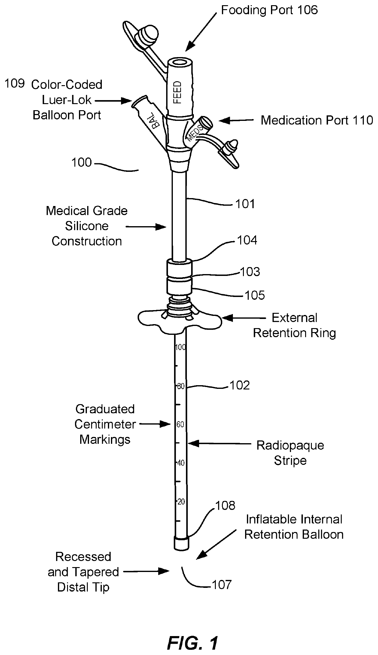
[0015]Medical tubing is often implanted into patients. Some medical tubing, such as feeding tubes and Foley catheters, have adaptions to retain the tubing in the desired position inside the patient. While such retention adaptations are normally useful, they can cause pain or even injury to the patient if the portion of the tubing outside the patient is inadvertently caught on an object and pulls the internal portion of the tubing out of the patient. For example, Foley catheters, which have an inflatable balloon to hold the catheter in a patient's bladder, also have an external section of tubing connecting to a urine collection bag. The external tubing section of a Foley catheter can catch on objects as the catheterized patient is being moved, suddenly jerking the catheter from the patient's bladder and causing injury to the patient's urethra (and, if the patient is a male, to the patient's prostate gland as well). Thus, reducing dislodgement of drainage catheters implanted in patien...


PUM


Abstract

The invention provides systems and methods for reducing injury to patients by dislodgement of implanted or attached medical tubing. The inventive systems and methods provide medical tubing with a releasable magnetic connection. When a stretching force is applied to the medical tubing that would cause the implanted or attached portion to be pulled or separated from the patient, the medical tubing instead separates at the point of the releasable magnetic connection, preventing the force from reaching the portion of the tubing implanted in or attached to the patient, thereby reducing the risk of injury to the patient. The releasable magnetic connection allows the tubing to be easily reconnected once the stretching force on the tubing has been terminated.

Description

CROSS-REFERENCE TO RELATED APPLICATIONS[0001]This application claims the benefit of and priority to U.S. Provisional Patent Application No. 62 / 731,038, filed Sep. 13, 2018, the contents of which are incorporated herein by reference for all purposes.STATEMENT OF FEDERAL FUNDING[0002]Not applicable.BACKGROUND OF THE INVENTION[0003]A variety of medical conditions, such as stroke, inability to swallow, or damage to the esophagus, can render patients unable for extended periods of time to tolerate oral feeding. Doctors typically treat such patients by introducing a gastrostomy tube, or “G tube,” through the abdominal wall into the patient's stomach, allowing the patient to be fed by passing pureed or liquid foods through the G tube into the stomach. Unfortunately, G tubes can be dislodged by being caught on clothing or objects as the patient moves around or, in the case of infants or persons with dementia, because the patient pulls at them. If such dislodgement occurs before a tract has ...

Claims


Application Information

Patent Timeline
IPC IPC(8): A61M39/10A61J15/00A61M27/00A61M25/00A61M16/04
CPCA61J15/0092A61M25/0017A61M2205/0288A61M27/00A61J15/0015A61M2205/0216A61J15/003A61M16/0465A61M39/10A61M16/04A61M16/0816A61J15/0073A61J15/0061A61J15/0049A61J15/0069A61J2200/70
Inventor RUFFOLO, LUIS IGNACIOWAKEMAN, DEREK S.
Owner UNIVERSITY OF ROCHESTER
Why Eureka
Try Eureka