
Piping elbow liners

Active Publication Date: 2005-03-31
TRONOX LLC
View PDF32 Cites 2 Cited by
  • Summary
  • Abstract
  • Description
  • Claims
  • Application Information

AI Technical Summary

Benefits of technology

[0003] An increase in the piping diameter requires an accompanying increase in the turning radius of any needed bends. The increase in turning radius in turn increases the space requirements for installing an elbow or bend needed to make a change in the fluid flow direction. Utilizing an elbow or bend with too small of a turning radius typically causes an undesirable pressure loss.

Problems solved by technology

However, circumstances frequently exist that impose constraints and preclude the use of standard piping elbows.
Utilizing an elbow or bend with too small of a turning radius typically causes an undesirable pressure loss.

Method used


Image

  • Piping elbow liners
  • Piping elbow liners
  • Piping elbow liners

Examples


Embodiment Construction

[0025] In the following detailed description of preferred embodiments of the present invention, reference is made to the accompanying Drawings, which form a part hereof, and in which are shown by way of illustration specific embodiments and contexts in which the present invention may be practiced. It should be understood that other embodiments may be utilized and changes may be made without departing from the scope of the present invention.

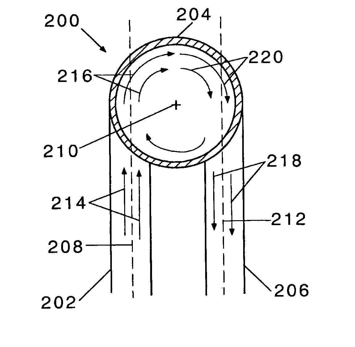
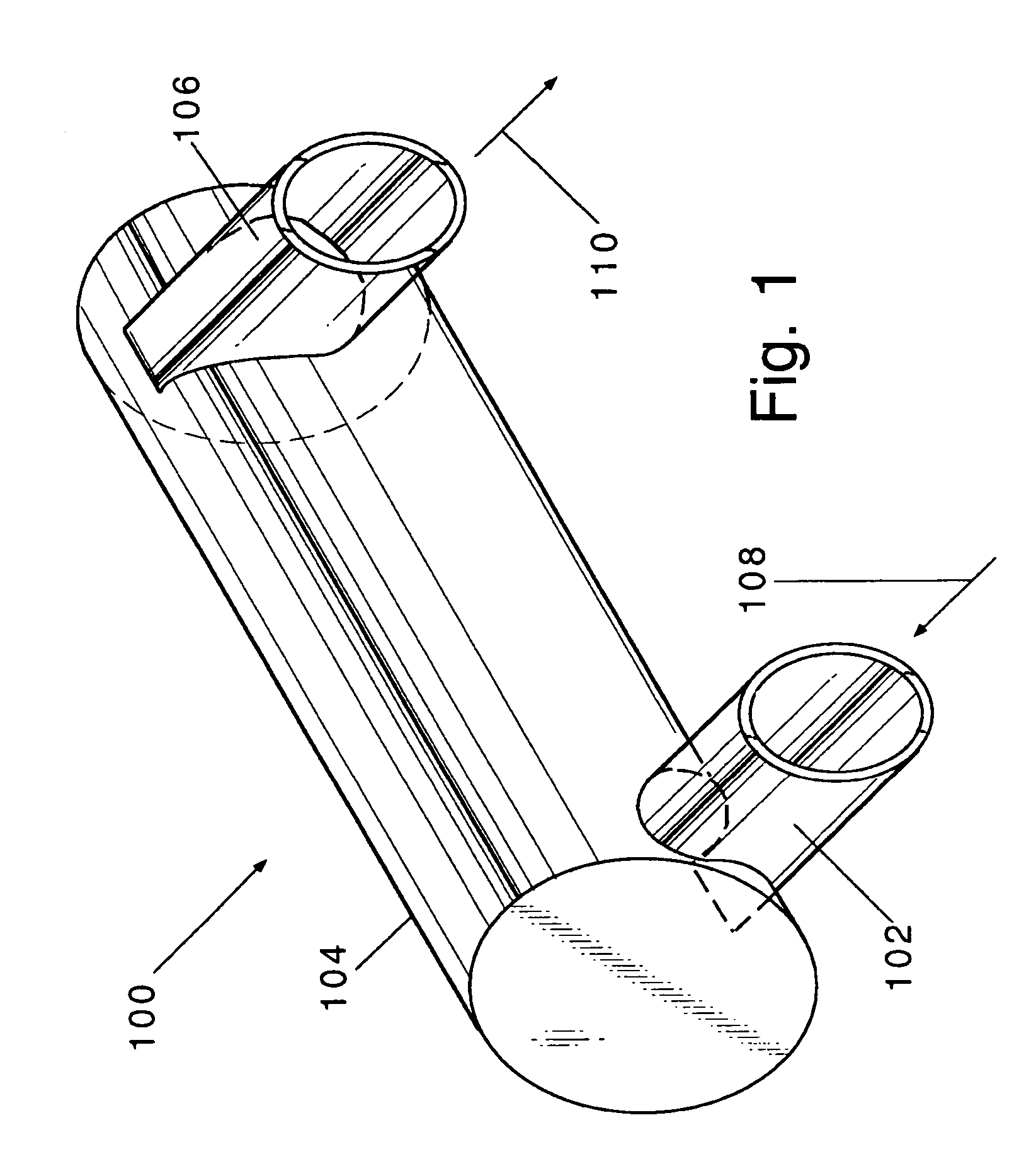
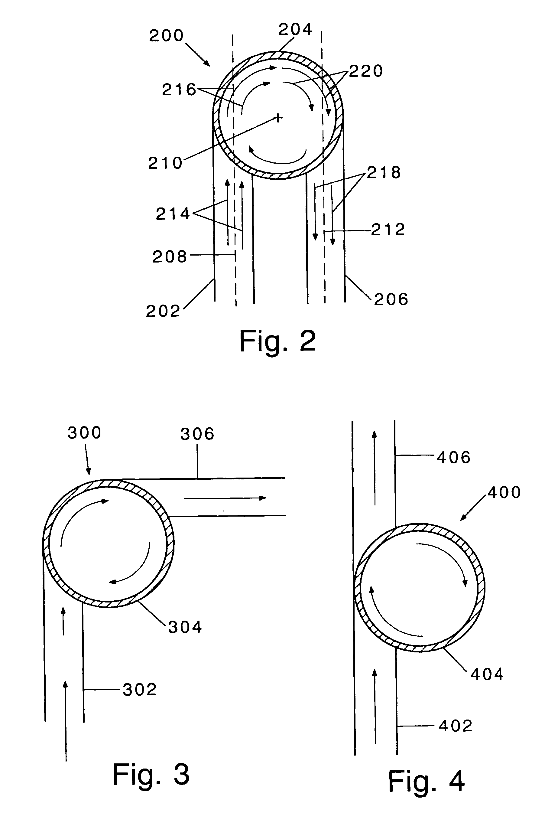
[0026] The piping elbows in which the present inventive liners are most preferably employed comprise a substantially-cylindrical body having a first end and a second end and having a substantially-constant diameter; a tangential inlet attached to the body section near the first end of the body section and having a diameter smaller than the diameter of the body section; and a tangential outlet attached to the body section near the second end of the body section and having a diameter smaller than the diameter of the body section. Unless specified o...


PUM

PropertyMeasurementUnit
Flow rateaaaaaaaaaa

Abstract

Liners useful as piping elbow liners comprising a body liner, a tangential inlet liner, and a tangential outlet liner. The tangential inlet liner and the tangential outlet liner can be removably inserted into a cavity in the body liner. The body liner can comprise two substantially-identical body section liners.

Description

FIELD OF THE INVENTION [0001] The present invention generally relates to apparatus for changing the direction of a fluid flow, especially of high temperature and / or highly abrasive fluid flows. More specifically, the present invention relates to such apparatus which employ a protective liner for protecting an outer pipe or vessel wall from direct exposure to such high temperature and / or highly abrasive fluid flows, for example, a refractory liner. BACKGROUND AND SUMMARY OF THE INVENTION [0002] In any enclosed system containing a flowing fluid, such as a piping system, there is frequently a need to make directional changes in the fluid flow. Typically, standard piping elbows, also referred to as bends, are used. However, circumstances frequently exist that impose constraints and preclude the use of standard piping elbows. These circumstances include the conveying of high temperature fluids, corrosive fluid streams, or abrasive fluid streams such as those that are particulate-laden fl...

Claims


Application Information

Patent Timeline
IPC IPC(8): F16L58/10F16L58/18
CPCF16L58/188F16L58/1036
Inventor FLYNN, HARRY EUGENEMARTIN, ROBERT O.NATALIE, CHARLES A.
Owner TRONOX LLC
Learn More