A turbine system

a turbine system and turbine technology, applied in the field of turbine systems, can solve the problems of not being able to restrict the increase of the torque to the crankshaft which is not always desirable, and the inability to control the flow of exhaust gas through the turbine, so as to reduce the risk of oscillation effectively, accurately control the back pressure, and the effect of bypassing the amoun

Active Publication Date: 2018-02-08
VOLVO LASTVAGNAR AB
View PDF4 Cites 0 Cited by
  • Summary
  • Abstract
  • Description
  • Claims
  • Application Information

AI Technical Summary

Benefits of technology

[0009]Preferably the pneumatic valve is an on / off valve. This is advantageous in that the pneumatic valve is operated in a robust manner since the pneumatic valve, when otherwise controlled variable thus allowing for intermediate positions between an open position and a closed position, may give rise to oscillations.
[0010]The turbine system may comprise a controller being connected to the flow control valve and to the on / off valve for regulating the valves. Back pressure and bypass amount is thereby controlled in a very efficient manner.
[0011]The controller may in some embodiments be configured to regulate the on / off valve in either a fully open position or in a closed position, thus reducing the risk for oscillations effectively.
[0012]The on / off valve may be an exhaust gas pressure regulator forming part of a diffuser for the exhaust gas flowing through the turbine system. The on / off valve is thereby implemented as an existing component in the exhaust gas flow path whereby the additional space required for such construction is greatly reduced.
[0013]The flow control valve is preferably continuously variable between two end positions. When the on / off valve is closed it is thereby possible to accurately control the back pressure, as well as the bypass amount, according to desired operating parameters.
[0014]The flow control valve may comprise a moving member which in a first end position is closing a bypass channel formed by said moving member, and which in a second end position is opening said bypass channel. The moving member may further be configured to move in a linear direction. The moving member may form part of a sliding wall, and the sliding wall may surround the on / off valve such that the bypass channel forms an annular channel radially outside the on / off valve. The flow control valve may consequently be provided in a robust manner, whereby the annular symmetric shape allows for efficient packaging and good aerodynamics.

Problems solved by technology

The turbocompound device of the above-described system will produce a torque increase to the crankshaft which is not always desirable.
Furthermore it is not possible to restrict the flow of exhaust gas through the turbine for engine braking.

Method used


Image

  • A turbine system
  • A turbine system
  • A turbine system

Examples


Embodiment Construction

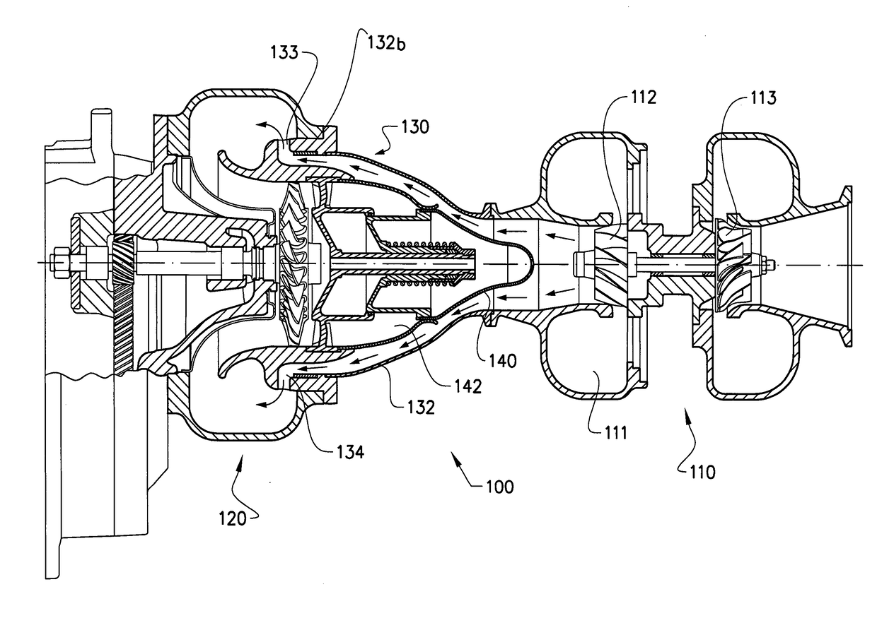
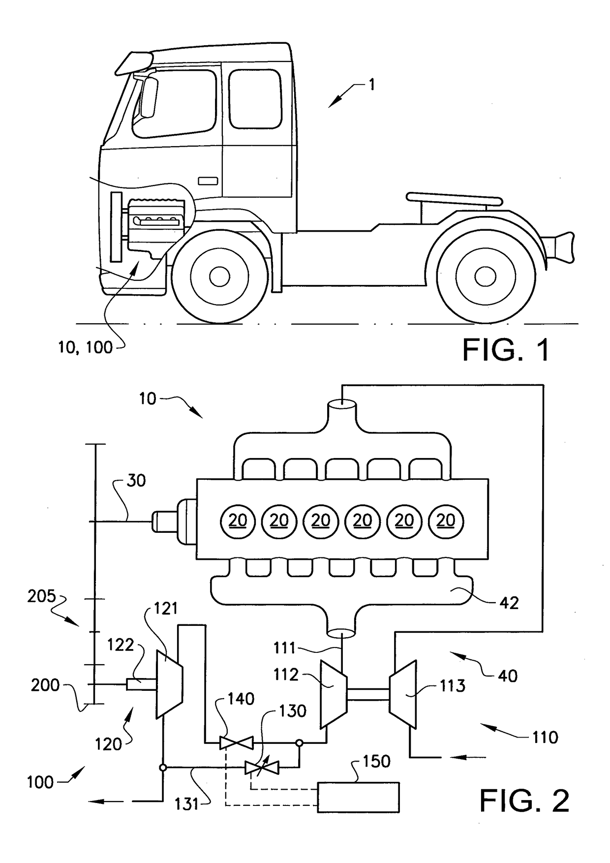
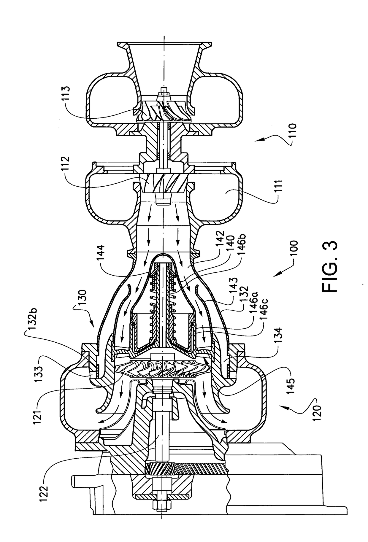
[0032]Starting with FIG. 1 a vehicle 1 is shown. The vehicle 1, which is illustrated as a truck, has an internal combustion engine 10 for driving the vehicle 1. As will be further explained below the internal combustion engine 0 of the vehicle 1 is provided with a turbine system 100 according to various embodiments. The vehicle 1 may have additional propulsion units, such as electric drives etc. as long as it has at least one engine providing a flow of exhaust gases interacting with the turbine system 100. Hence the vehicle 1 is not exclusively a truck but may also represent various heavy duty vehicles such as buses, constructional equipment, etc.

[0033]In FIG. 2 an example of an internal combustion engine 10 is shown. The internal combustion engine 10 includes a plurality of cylinders 20 operated to combust fuel, such as diesel or gasoline, whereby the motion of pistons reciprocating in the cylinders 20 is transmitted to a rotation movement of a crank shaft 30. The crank shaft 30 is...


PUM


Abstract

A turbine system for recovering energy of exhaust gases of an internal combustion engine is provided. The turbine system includes a first turbine device, a second turbine device, and a flow control valve for bypassing exhaust gases passed the second turbine device. The turbine system further includes a pneumatic valve arranged between the first turbine device and the second turbine device and being configured to control the flow of exhaust gas to the second turbine device.

Description

BACKGROUND AND SUMMARY[0001]The invention relates to a turbine system for recovering energy of exhaust gases of an internal combustion engine. More particularly the present invention relates to improvements of such turbine systems.[0002]The invention can be applied in heavy-duty vehicles, such as trucks, buses and construction equipment. Although the invention will be described with respect to a truck, the invention is not restricted to this particular vehicle, but may also be used in other applications utilizing turbine systems such as aero or marine systems.[0003]Vehicles may be provided with turbine systems for recovering energy of the exhaust gas flow from an internal combustion engine. A turbine system may e.g. include a turbocharger which purpose is to convert the energy of the exhaust gas into a pressure increase of the intake air to the internal combustion engine, and a turbocompound unit which purpose is to convert the remaining energy into a rotational movement of a shaft....

Claims


Application Information

Patent Timeline
Patent Type & Authority Applications(United States)
IPC IPC(8): F01D17/14F01D17/10F02B41/10F02B37/00F02B37/18
CPCF01D17/143F02B37/004F02B37/183F02B41/10F01D17/105F05D2220/40F02B37/013Y02T10/12
Inventor ERIKSSON, PONTUS
Owner VOLVO LASTVAGNAR AB
Why Eureka
Try Eureka