

Electric oil pump
- Summary
- Abstract
- Description
- Claims
- Application Information
AI Technical Summary
Benefits of technology
Problems solved by technology
Method used
Image

Examples
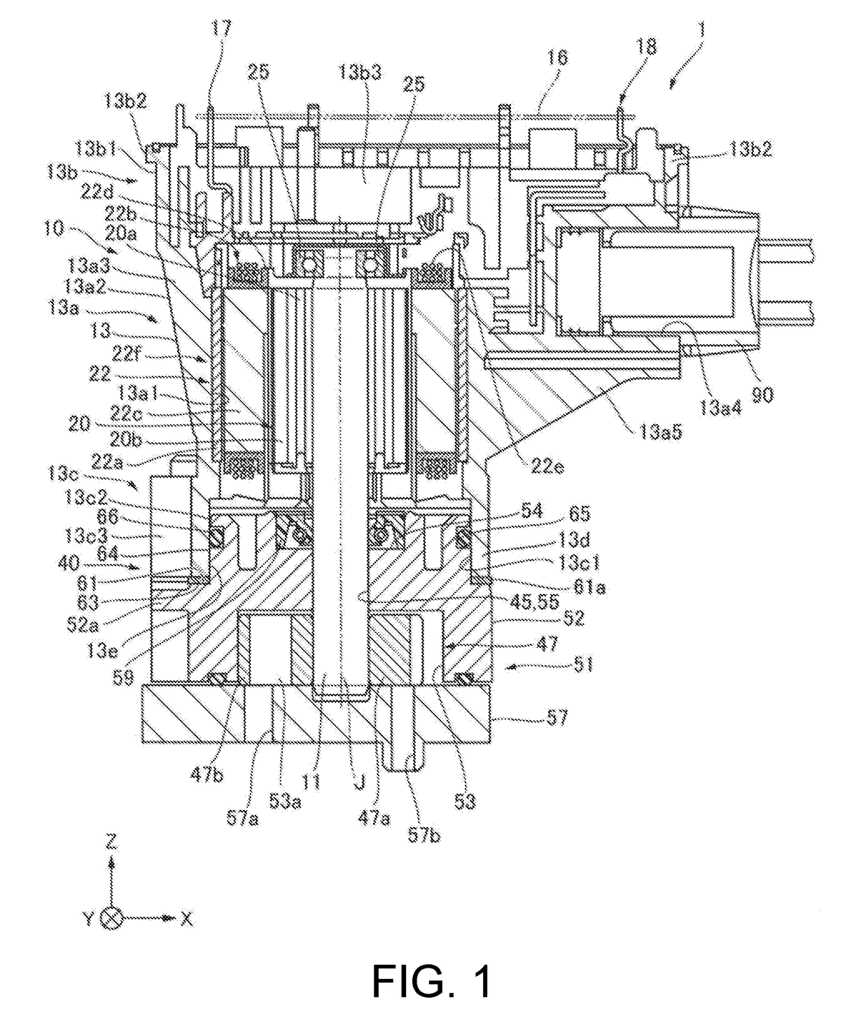
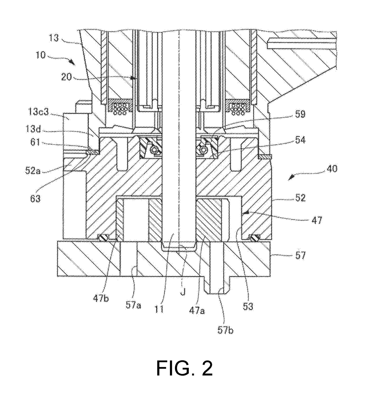
first embodiment
Modified Examples of First Embodiment
Modified Example in Which Housing Part 53 is Provided in Pump Cover 57
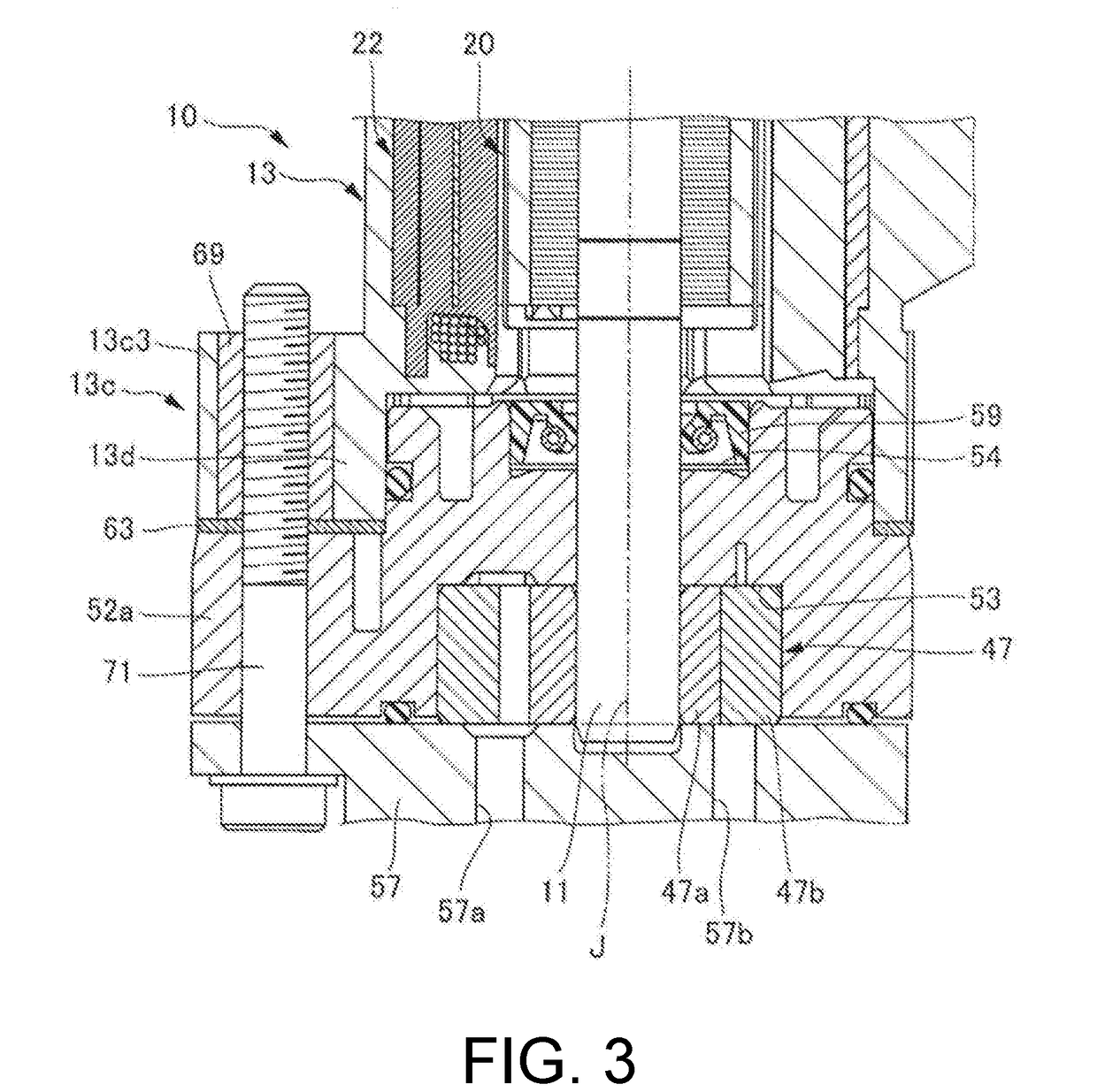
[0063]The housing part 53 according to the first embodiment shown in FIG. 1 is provided in the pump body 52 of the pump unit 40. However, the present disclosure is not limited to this structure. For example, as shown in FIG. 4, the housing part 53 may be provided in the pump cover 57 (Modified Example 1).
[0064]The pump cover 57 has the housing part 53 which is recessed from the other side surface in the axial direction to one side in the axial direction and in which the pump rotor 47 is housed. In addition, the step 61 is recessed inwardly in the radial direction of the pump body 52 on the outer surface outside the pump body 52 in the radial direction. The front side end 13d of the resin housing 13 is fixed to the step 61.
[0065]In this modified example, since the housing part 53 is provided in the pump cover 57, the step 61 is provided on the outer surface of the pump body 52, ...
PUM
 Abstract
Description
Claims
Application Information