Substrate storing case, substrate cleaning apparatus and substrate storing case cleaning apparatus

a cleaning apparatus and substrate technology, applied in the direction of containers preventing decay, instruments, separation processes, etc., can solve the problems of substrate damage, difficult to remove, and the substrate storing case cannot be heated to 100 degrees c. or higher

Inactive Publication Date: 2015-09-17
KK TOSHIBA
View PDF2 Cites 6 Cited by
  • Summary
  • Abstract
  • Description
  • Claims
  • Application Information

AI Technical Summary

Problems solved by technology

Such defects of a substrate can be caused not only by particles adhering to the substrate but also impurities or nanoparticles in the environment to which the substrate is exposed.
However, when the substrate storing case made of polycarbonate is cleaned, the substrate storing case cannot be heated to 100 degrees C. or higher because of the heat resistance of polycarbonate.
Therefore, there is a problem that it is difficult to remove, by heating, impurities or the like from the environment that adhere to the substrate storing case made of a resin.

Method used


Image

  • Substrate storing case, substrate cleaning apparatus and substrate storing case cleaning apparatus
  • Substrate storing case, substrate cleaning apparatus and substrate storing case cleaning apparatus
  • Substrate storing case, substrate cleaning apparatus and substrate storing case cleaning apparatus

Examples


first embodiment

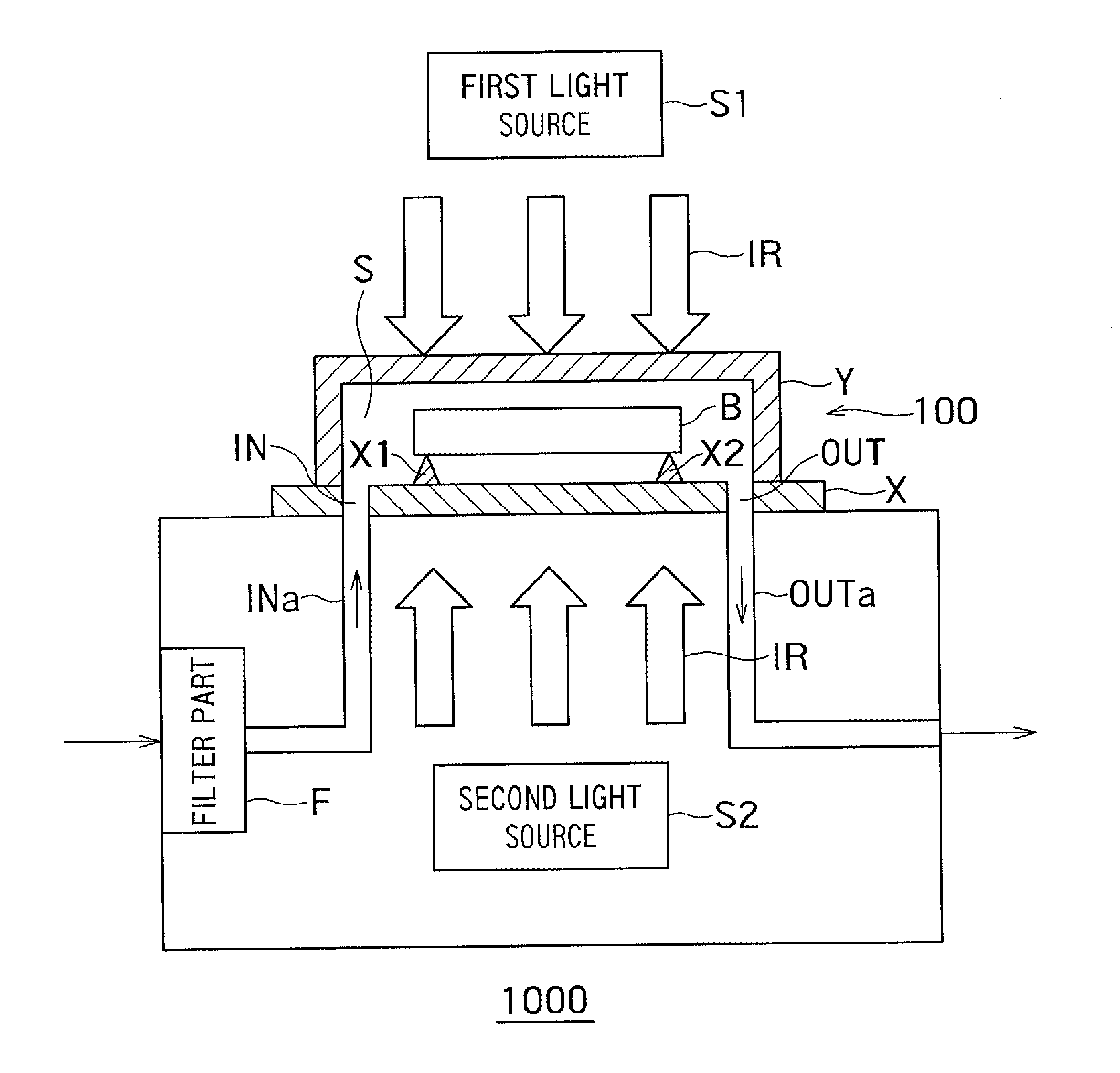
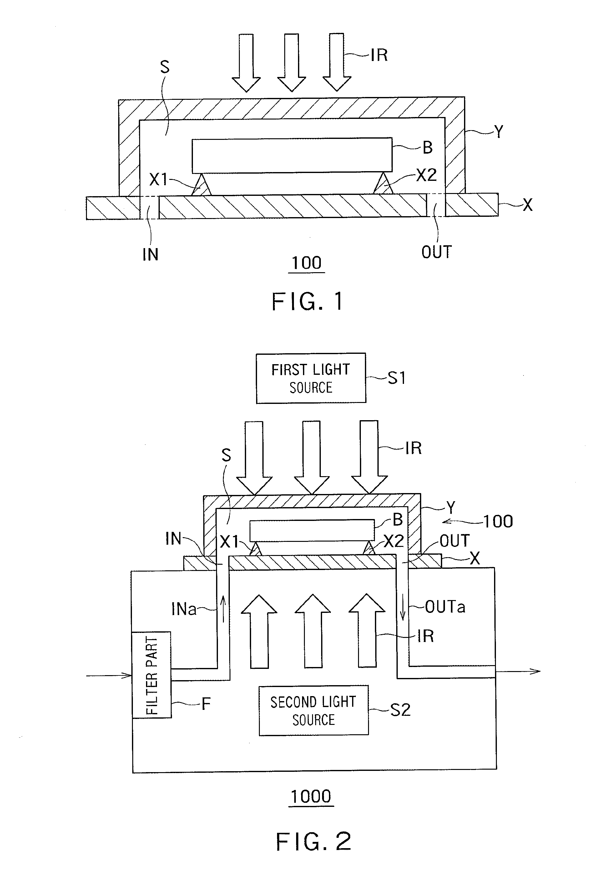
[0021]FIG. 1 is a diagram showing an example of a configuration of the substrate storing case 100 according to a first embodiment.

[0022]As shown in FIG. 1, the substrate storing case 100 that stores a substrate “B” includes a base “X” and a top cover “Y”.

[0023]The base “X” is made of quartz glass, which transmits infrared rays “IR”. The base “X” has supporting parts “X1” and “X2” that support the substrate “B” from below on the upper surface thereof.

[0024]The top cover “Y” is also made of quartz glass, which transmits infrared rays “IR”. The top cover “Y” is in contact with the base “X” when the top cover “Y” covers the substrate “B” on the base “X”.

[0025]The substrate “B” is held inside the substrate storing case 100 and thereby separated from the outside air.

[0026]As shown in FIG. 1, the base “X” has an intake port “IN” that is in communication with a space “S” enclosed by the base “X” and the top cover “Y” and is capable of being opened and closed and an outlet port “OUT” that is...

second embodiment

[0063]In a second embodiment, an example of a configuration of a substrate storing case in the case where the substrate has a recess formed in the middle of the lower surface will be described.

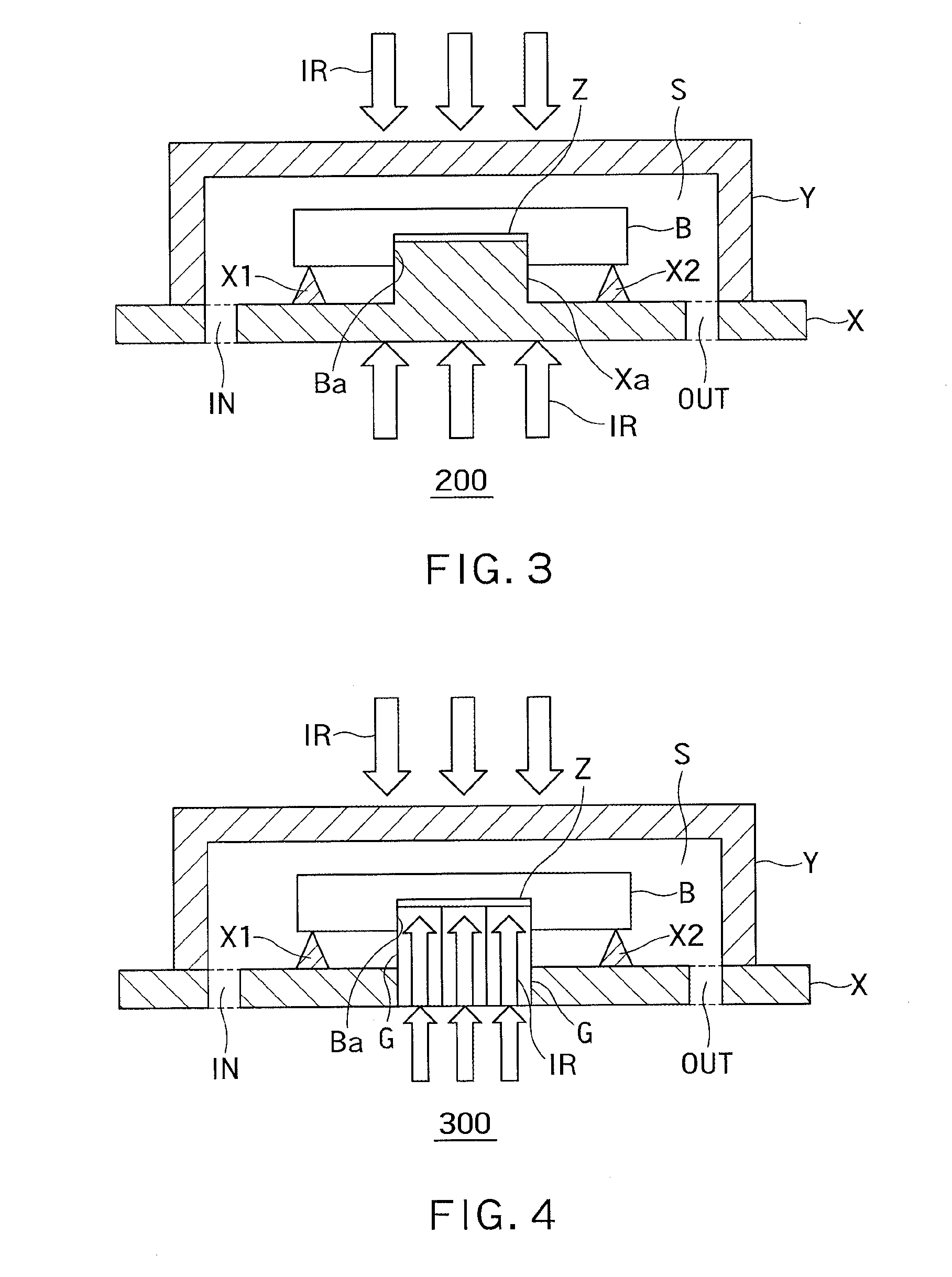
[0064]FIG. 3 is a diagram showing an example of a configuration of a substrate storing case 200 according to the second embodiment. In FIG. 3, the same reference symbols as those in FIG. 1 denote the same components as those in the first embodiment. The substrate storing case 200 shown in FIG. 3 is used with the substrate cleaning apparatus 1000 shown in FIG. 2, as with the substrate storing case 100 according to the first embodiment.

[0065]As shown in FIG. 3, the substrate “B” has a recess “Ba” formed in the middle of the lower surface thereof. In the example shown in FIG. 3, the substrate (lithography original plate) “B” is a template for nanoimprint.

[0066]The base “X” has a projection “Xa”, which is shaped to conform to the recess “Ba” of the substrate “B”, formed on the upper surface thereo...

third embodiment

[0076]In a third embodiment, an example of a configuration of another substrate storing case in the case where the substrate “B” has the recess “Ba” formed in the middle of the lower surface will be described.

[0077]FIG. 4 is a diagram showing an example of a configuration of a substrate storing case 300 according to the third embodiment. In FIG. 4, the same reference symbols as those in FIG. 3 denote the same components as those in the second embodiment. The substrate storing case 300 shown in FIG. 4 is used with the substrate cleaning apparatus 1000 shown in FIG. 2, as with the substrate storing case 200 according to the second embodiment.

[0078]As shown in FIG. 4, the substrate “B” has the recess “Ba” formed in the middle of the lower surface thereof.

[0079]The base “X” has a light guide “G”, which is shaped to conform to the recess “Ba” of the substrate “B”, formed in the middle thereof. That is, the substrate storing case 300 differs from the substrate storing case according to th...


PUM

PropertyMeasurementUnit
sizesaaaaaaaaaa
heat resistanceaaaaaaaaaa
adhesionaaaaaaaaaa

Abstract

The substrate storing case includes a base being made of quartz glass, and having a supporting part that is formed on an upper surface thereof and supports a substrate. The substrate storing case includes a top cover being made of quartz glass, and being in contact with the base to cover the substrate on the upper surface of the base. The substrate includes a first absorptive member that absorbs infrared rays and generates heat. The base or the top cover has an intake port that is in communication with a space enclosed by the upper surface of the base and the top cover and is capable of being opened and closed, and an outlet port that is in communication with the space and is capable of being opened and closed.

Description

CROSS-REFERENCE TO RELATED APPLICATION[0001]This application is based upon and claims the benefit of priority from the prior Japanese Patent Application No. 2014-050857, filed on Mar. 13, 2014, the entire contents of which are incorporated herein by reference.BACKGROUND[0002]1. Field[0003]Embodiments described herein relate generally to a substrate storing case, a substrate cleaning apparatus and a substrate storing case cleaning apparatus.[0004]2. Background Art[0005]With the recent advance of pattern micromachining, the manufacturing cost has become more dependent on the problem of defects of a substrate (lithography original plate).[0006]Such defects of a substrate can be caused not only by particles adhering to the substrate but also impurities or nanoparticles in the environment to which the substrate is exposed.[0007]Therefore, it is increasingly important to control impurities in the environment to which the substrate is exposed or to control particles having sizes on the ord...

Claims


Application Information

Patent Timeline
Patent Type & Authority Applications(United States)
IPC IPC(8): A61L2/04B65D81/30A61L2/08B65D25/10B01D46/00B08B7/00B65D13/02B65D81/18
CPCA61L2/04B65D13/02B65D81/30A61L2/085B65D25/10B01D46/00B08B7/005B65D81/18B08B7/0071B08B9/00G03F1/82G03F1/66
Inventor OPPATA, YUKIOSAKURAI, HIDEAKIKANAMITSU, SHINGOTSUTSUI, TOMOHIROHAGIHARA, KAZUKI
Owner KK TOSHIBA
Why Eureka
Try Eureka