
Structure for a Multi-Surface Magnetic Block

a technology of magnetic blocks and structures, applied in the field of splicing blocks, can solve the problems of unfavorable batch production and relative difficulty in mold development, and achieve the effects of improving the manufacturing efficiency of blocks, reducing the number of splicing blocks, and ensuring the quality of splicing blocks

Inactive Publication Date: 2015-09-17
WEI ZHENGPENG
View PDF2 Cites 22 Cited by
  • Summary
  • Abstract
  • Description
  • Claims
  • Application Information

AI Technical Summary

Benefits of technology

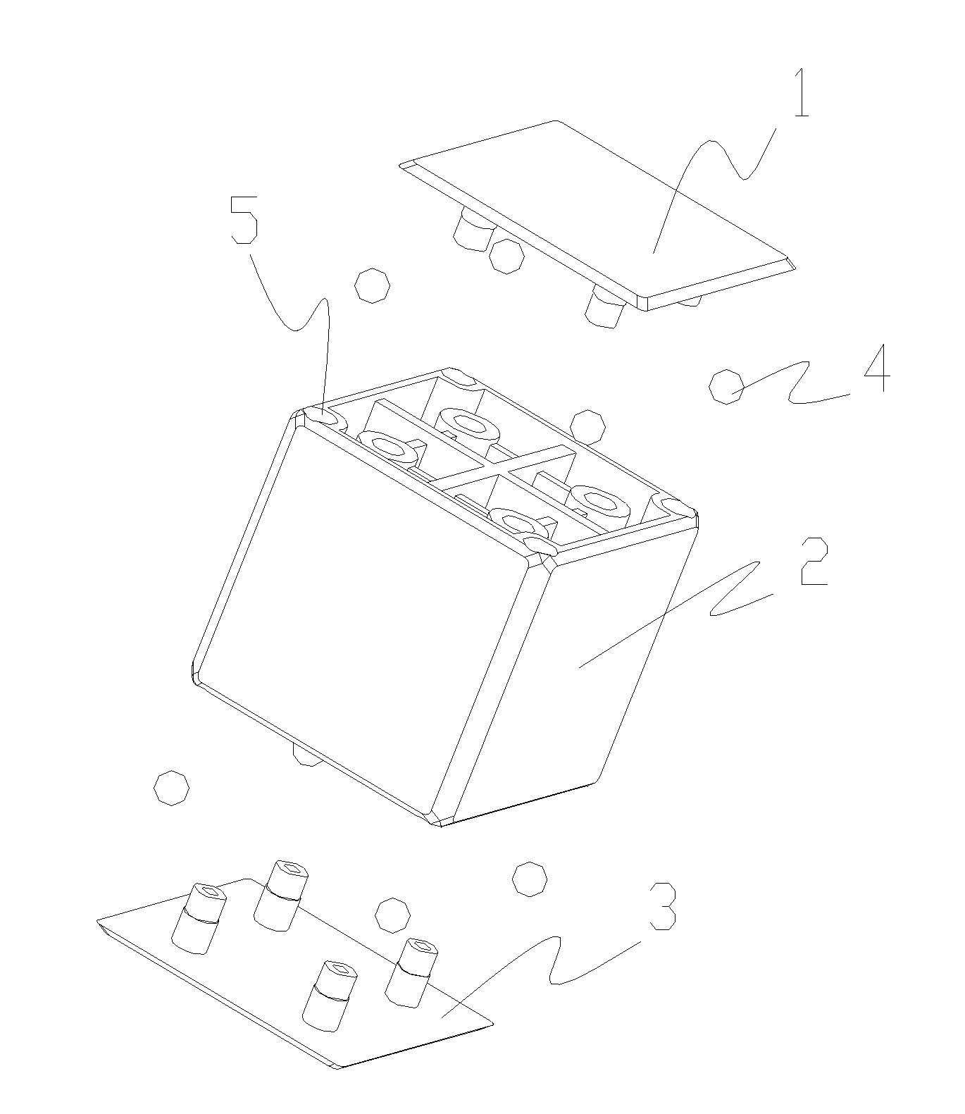
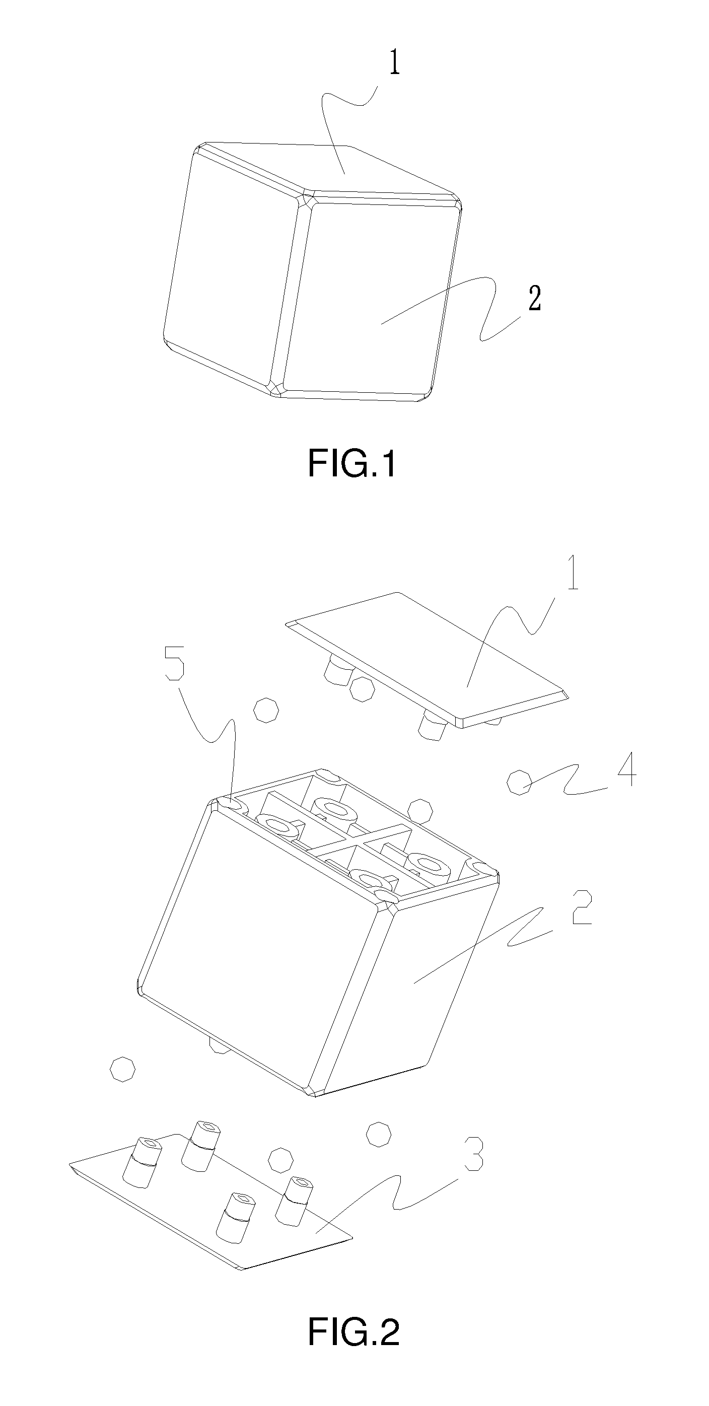
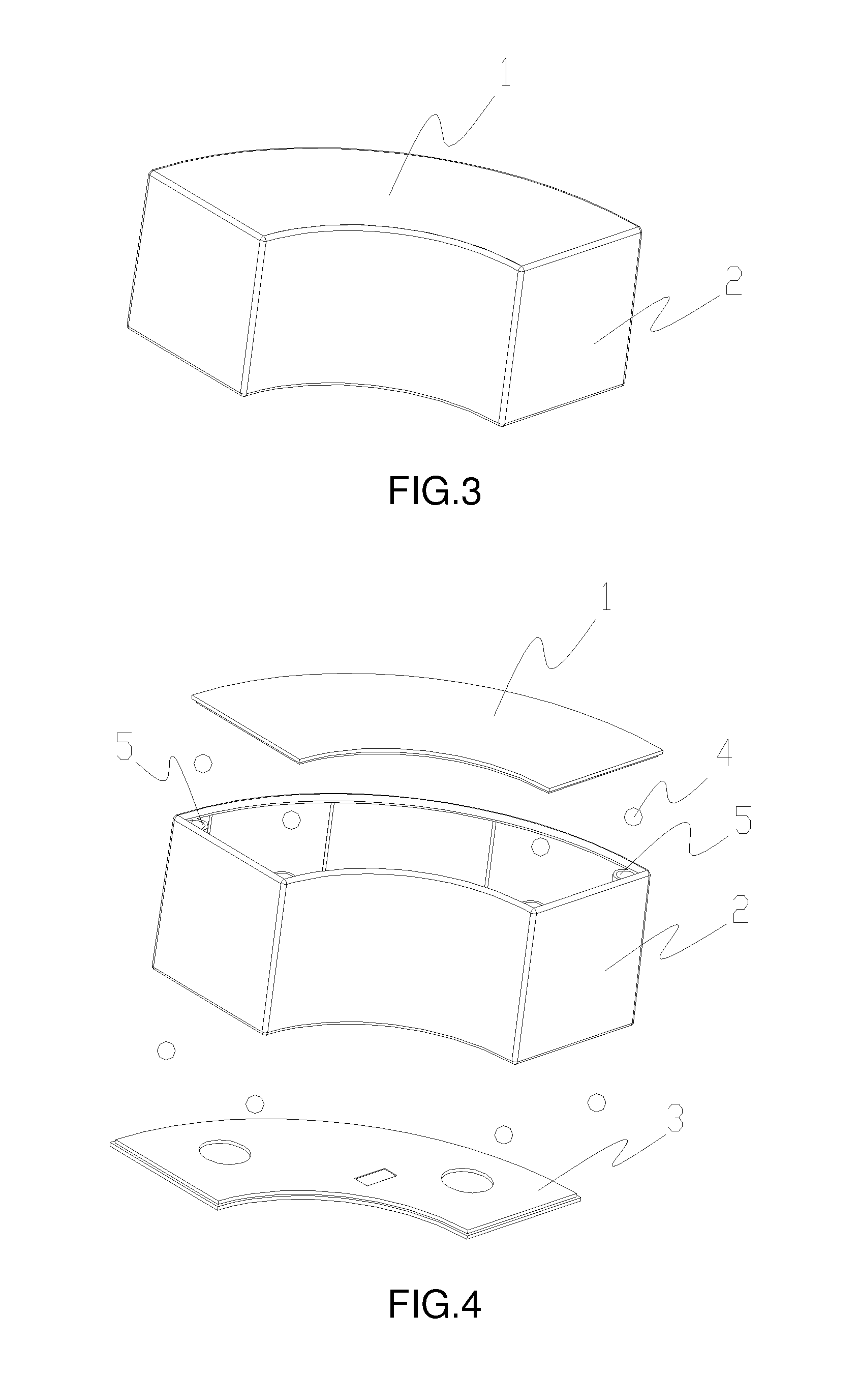
The present invention aims to provide a multi-surface magnetic block with an optimized structure that is easy to manufacture and assemble. The block is made up of a main housing body and sealing covers that are fixedly connected to form the whole block. The magnetic assemblies embedded in the block consist of spherical ball magnets and cavities that are distributed at positions adjacent to the sealing covers and encapsulated as closed cavities after the sealing covers are fixed onto the main housing body. The ball magnets are embedded in the closed cavities with free rotation, allowing for the adjustment of magnetic pole directions. This structure allows for stable and reliable attachment among blocks, ensuring magnetic function, and is easy to manufacture, assemble, and install. Overall, this solution improves manufacturing efficiency, reduces manufacturing difficulty and cost, and has practical application in various fields.

Problems solved by technology

However, such blocks suffer from the following disadvantages during the manufacturing: numerous and jumbled working procedures, and relatively difficult development of molds, which disadvantages are not favorable for batch productions.

Method used


Image

  • Structure for a Multi-Surface Magnetic Block
  • Structure for a Multi-Surface Magnetic Block
  • Structure for a Multi-Surface Magnetic Block

Examples


Embodiment Construction

[0029]The present invention relates to a structure for a multi-surface magnetic block, wherein the block is a polyhedron, as shown in FIGS. 1, 3, 5, 7, 9, 11, 13, and 15, can be a cube, a sector, or a trapezoid, etc.; specific shapes can be designed according to toy needs. The main objective of the present invention is to reduce manufacturing difficulty and cost of magnetic blocks, thereby realizing batch production of blocks with high efficiency, high yield rate and low cost.

[0030]The blocks of the present invention are embedded with magnetic assemblies, as shown in FIGS. 1 to 16, via which magnetic assemblies any two blocks can be attached and spliced with each other; the block is formed by assembling sealing covers and a main housing body 2, wherein the sealing covers can be a single sealing cover, can also be an upper cover 1 and a bottom cover 3, and can also be more sealing covers, depending on specific block structures; the sealing covers are fixedly connected to the main hou...


PUM

PropertyMeasurementUnit
structureaaaaaaaaaa
magneticaaaaaaaaaa
stereoscopic structureaaaaaaaaaa

Abstract

The present invention discloses a structure for a multi-surface magnetic block, embedded with magnetic assemblies, wherein the block is embedded with magnetic assemblies, via which assemblies any two blocks can be attached and spliced with each other; the block is formed by assembling sealing covers and a main housing body, and the sealing covers are fixedly connected to the main housing body to form the whole block; the magnetic assemblies are constituted by spherical ball magnets and cavities, the cavities are distributed at the positions in the main housing body adjacent to the sealing covers, and the cavities are encapsulated to be closed cavities after the sealing covers are fixed onto the main housing body; the ball magnets are embedded in the closed cavities with free rotation. The solution greatly improves block manufacturing efficiency, and reduces manufacturing difficulty and cost, thereby having an enhanced practicability and a great market value.

Description

BACKGROUND OF THE INVENTION[0001]The present invention relates to the technical field of splicing blocks, in particular, toy-dedicated and education-dedicated splicing blocks, to be more specific, magnetic splicing blocks characterized by teaching in joy.[0002]Previously, the invention applicant put forward a wholly new magnetic block different from traditional blocks. Such magnetic block is provided with magnetic assemblies on every surface; multiple surfaces of any block can be engaged in outward magnetic splicing in any direction, and splicing manners are diversified, such that numberless splicing shapes can be realized and transformed. Moreover, the magnetic manner enables the splicing to be more relax and interesting, capable of better helping children to not only acquire knowledge but also enjoy themselves while stacking up blocks, thereby really realizing the educational ideal of teaching in joy. In addition, due to adoption of magnetic assemblies, such magnetic blocks can be...

Claims


Application Information

Patent Timeline
Patent Type & Authority Applications(United States)
IPC IPC(8): A63H33/04A63H33/26A63H33/06H01F7/02
CPCA63H33/046A63H33/06A63H33/26H01F7/02H01F7/0221
Inventor WEI, ZHENGPENG
Owner WEI ZHENGPENG
Learn More