Modeling intersecting faults and complex wellbores in reservoir simulation

a reservoir simulation and fault technology, applied in image data processing, analogue and hybrid computing, fluid removal, etc., can solve the problems of complex internal geometry and boundaries that exist simulation technology which uses structured grids or cpg grids cannot adequately represent, and the cpg grid has severe representation difficulties

Active Publication Date: 2015-09-17
SAUDI ARABIAN OIL CO
View PDF9 Cites 27 Cited by
  • Summary
  • Abstract
  • Description
  • Claims
  • Application Information

AI Technical Summary

Benefits of technology

[0014]The present invention also provides a new and improved data storage device having stored in a non-transitory computer readable medium computer operable instructions for causing a data processing system to generate an unstructured grid of a model of a subsurface reservoir based on input data defining internal boundary geometry and internal boundary descriptions of the reservoir model, and on well trajectory and completion data for wells in the reservoir model. The instructions stored in the data storage device causing the data processing system to refine the internal boundary geometry data to produce grid cell points for the grid, and build internal boundary lines connecting adjacent grid cell points to form boundary line segments. The instructions also cause the data processing system to construct internal boundary intersected circles at the grid cell points, generate internal boundary grid points between intersections of internal boundary intersected circles of adjacent grid cell points, and prioritize the generated internal boundary grid points. The instructions also cause the data processing system to generate well points in the reservoir model, and to prioritize the generated well points. The instructions then cause the data processing system to resolve conflicting grid points between the generated internal boundary grid points and the generated well grid points. The instructions then cause the data processing system to perform unconstrained Delaunay triangulation on the resolved grid points, form a perpendicular bisection grid of the resolved grid points to form a Voronoi grid of data for the reservoir cells, and form an unstructured grid data description for the Voronoi grid.

Problems solved by technology

Existing simulation technology which uses structured grids or CPG grids cannot represent these complex internal geometry and boundaries adequately.
The CPG grid has severe difficulties in representing faults with complex intersecting geometry in portions of the reservoir grid.
Use of the CPG grid can result in awkward pinching areas, and the resulting grid can be highly non-orthogonal.
Unfortunately, the resulting linear system can be much more difficult and / or time consuming to solve.
It is usually computationally expensive, especially for large simulation models.
Additionally, it leads to congested grid regions in order to satisfy boundaries but at the cost of lessened discretization, and less satisfactory convergence for reservoir simulation.
As a consequence, such undesired triangles increased modeling complexity and introduced numerical errors which eventually led to poor discretization and poor computational efficiency during flow simulation.

Method used


Image

  • Modeling intersecting faults and complex wellbores in reservoir simulation
  • Modeling intersecting faults and complex wellbores in reservoir simulation
  • Modeling intersecting faults and complex wellbores in reservoir simulation

Examples


Embodiment Construction

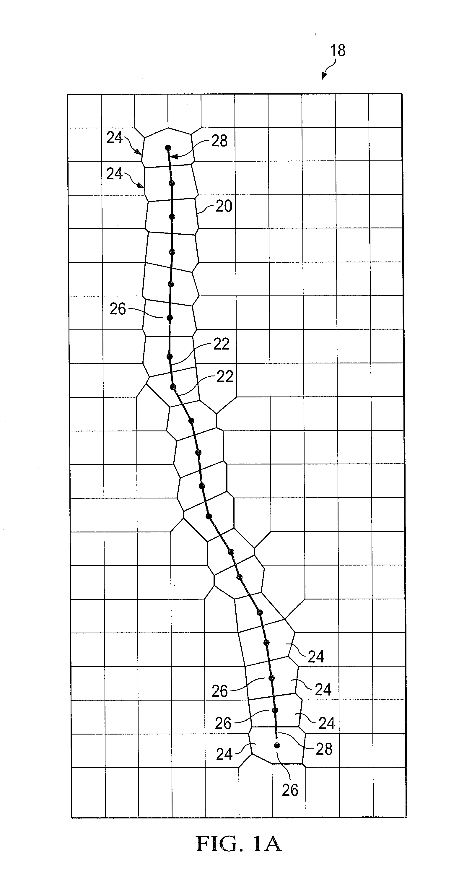
[0037]In the drawings, FIG. 1A illustrates a Voronoi cell diagram 18 for a boundary grid 20, in which is formed according to Applicant's related co-pending U.S. patent application Ser. No. 14 / 171,815, previously referenced, a model of a complex wellbore 22. According to such application, the wellbore 22 is taken as an internal boundary in the reservoir, and Voronoi cells 24 are generated by aligning cell centers 26 on the wellbore trajectory path 28. In the context of the present invention, internal boundaries according to Applicant's related co-pending U.S. patent application are referred to as Type 1 boundaries.

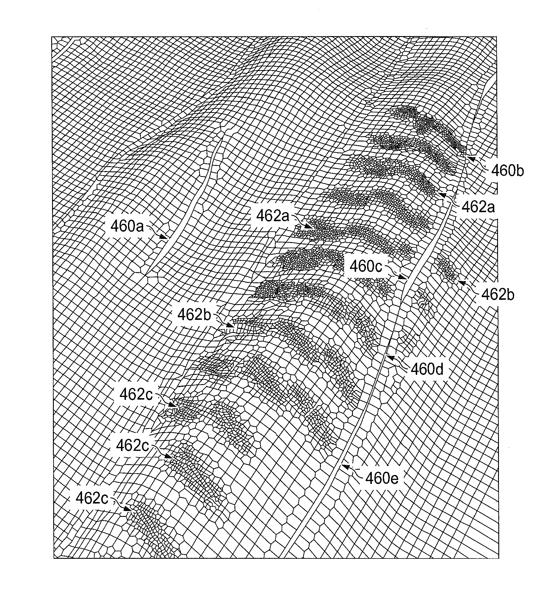
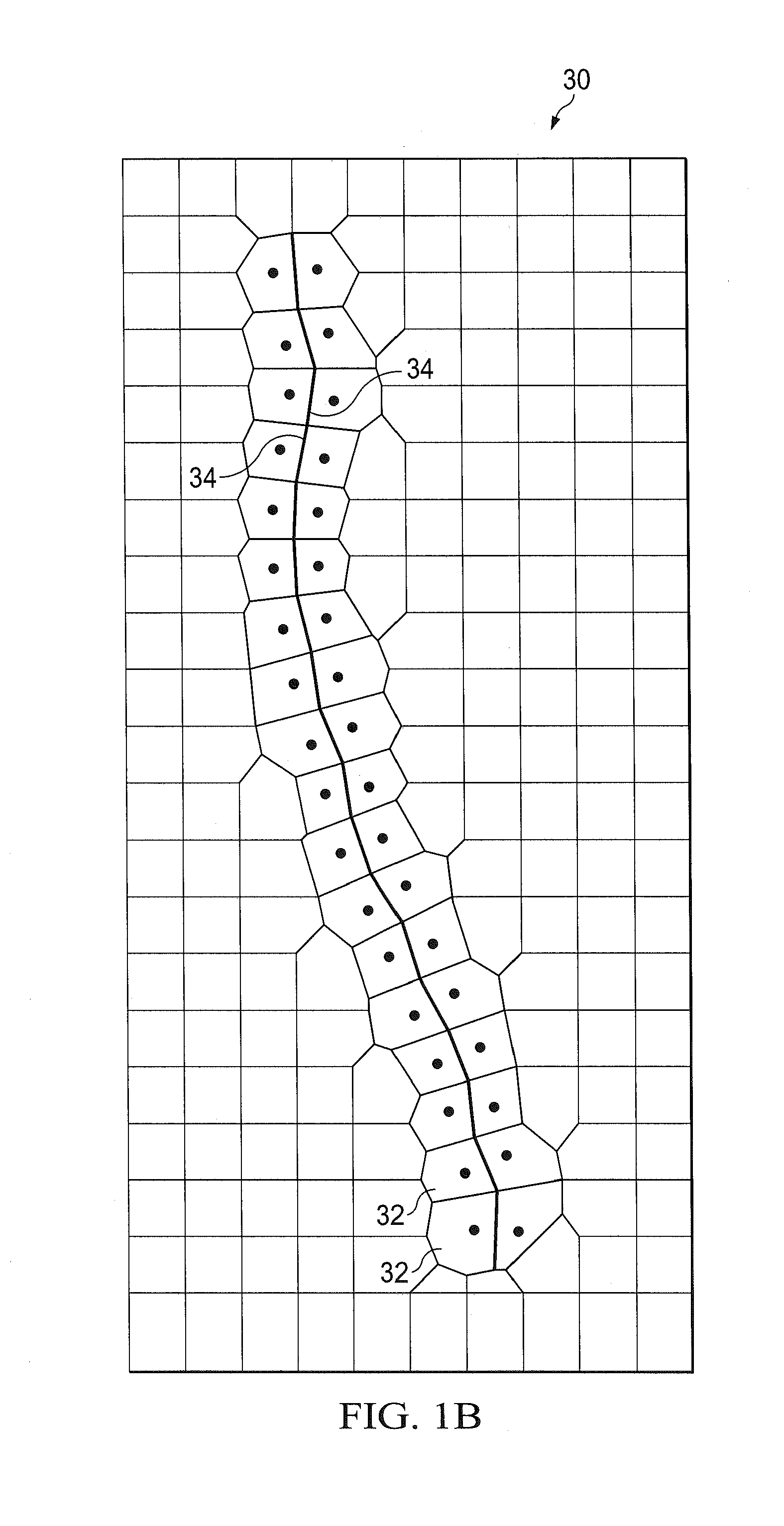
[0038]In FIG. 1B illustrates a Voronoi cell diagram 30 for a boundary grid 32, in which is formed according to Applicant's companion U.S. patent application Ser. No. 14 / 215,851, filed of even date herewith as referenced, a model of a fault line 34. According to such application, the boundary grid 30 is formed where the Voronoi cell edges align with an internal boundary. The...


PUM


Abstract

Orthogonal unstructured grids are automatically constructed for a field or reservoir model with two types of internal boundaries: complex wells and faults, or other discontinuities. The methodology is used to constructed simulation grids for reservoirs or fields which contains both complex fault planes and multi-lateral wells. A hierarchical grid point generation, prioritization, conflict point removal system is provided enabling the use of unconstrained Delaunay triangulation. High-quality orthogonal unstructured grids are produced with good convergence properties for reservoir simulation.

Description

CROSS REFERENCE TO RELATED APPLICATIONS[0001]The present application relates to modeling for reservoir simulation, as do Applicant's prior co-pending U.S. patent application Ser. No. 14 / 171,815, “Systems, Methods, and Computer-Readable Media for Modeling Complex Wellbores in Field-Scale Reservoir Simulation,” filed Feb. 4, 2014, based on U.S. Provisional Patent Application No. 61 / 766,056, “Systems, Methods, and Computer-Readable Media for Modeling Complex Wellbores in Field-Scale Reservoir Simulation,” filed Feb. 18, 2013 (SA 5125); and Applicant's companion U.S. patent application Ser. No. 14 / 215,851, “Generating Unconstrained Voronoi Grids In A Domain Containing Complex Internal Boundaries”, (SA 5263) filed of even date herewith. Each of these related applications is incorporated herein by reference for all purposes.BACKGROUND OF THE INVENTION[0002]1. Field of the Invention[0003]The present invention relates to modeling in reservoir simulation, and more particularly to modeling in...

Claims


Application Information

Patent Timeline
Patent Type & Authority Applications(United States)
IPC IPC(8): E21B43/00
CPCE21B43/00E21B41/00G06Q50/02G06T17/05G06T17/20G01V99/00G01V2210/66G06F30/23G01V99/005G01V2210/642E21B2200/20G06F30/13
Inventor FUNG, LARRY SIU-KUENDING, XIANG YANGDOGRU, ALI H.
Owner SAUDI ARABIAN OIL CO
Why Eureka
Try Eureka