System and Method for Lateral Flow Immunoassay Testing

a technology of immunoassay and lateral flow, applied in the field of system, can solve the problems of speed trading, incorrect interpretation, accuracy or reliability, and the range of complexity of screening tests for the detection of drugs of abuse and other analytes

Active Publication Date: 2015-09-17
HEALGEN SCI LLC
View PDF2 Cites 9 Cited by
  • Summary
  • Abstract
  • Description
  • Claims
  • Application Information

AI Technical Summary

Benefits of technology

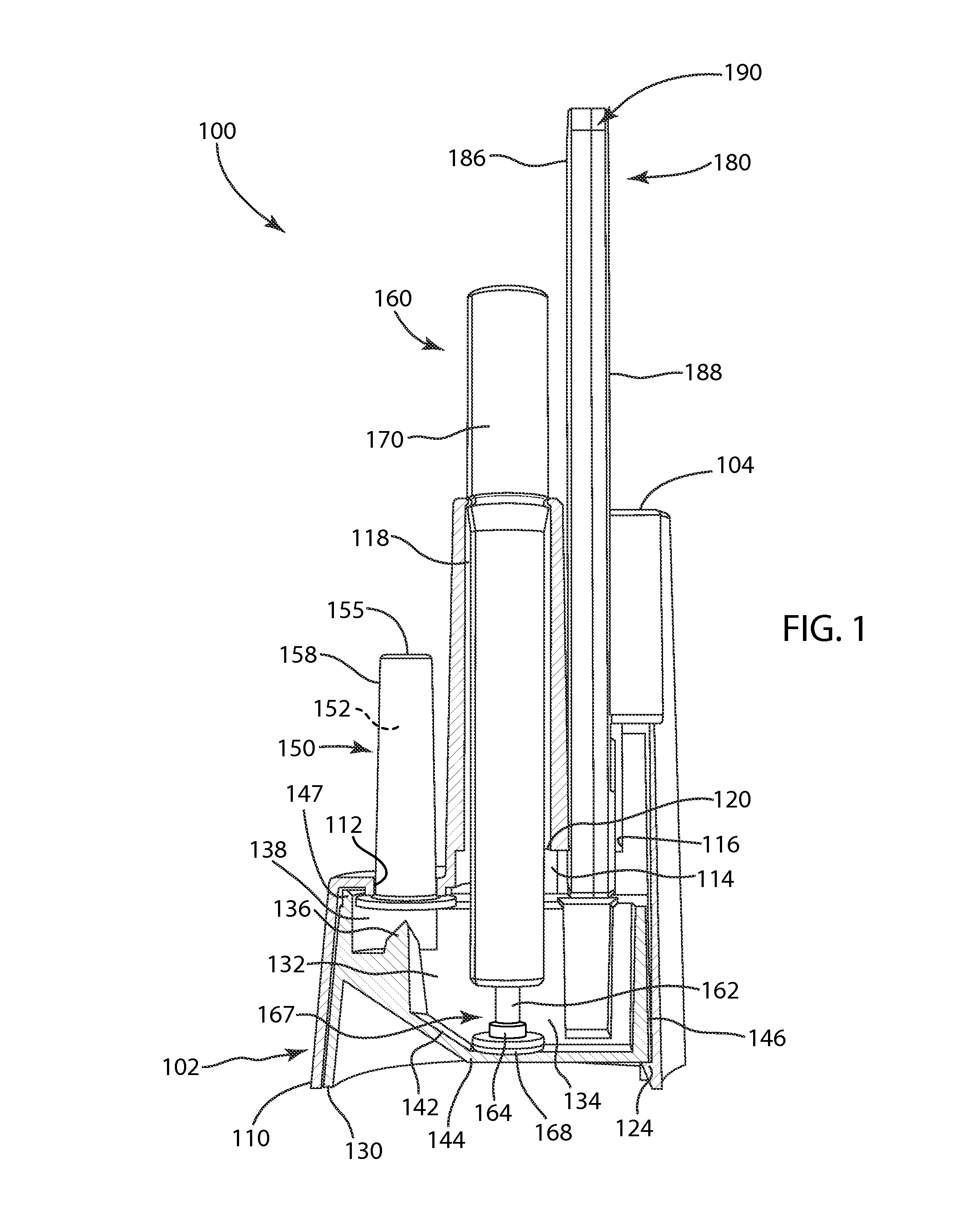
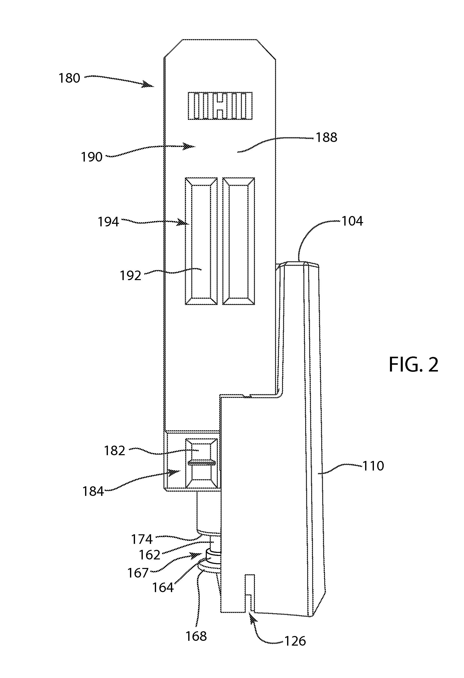
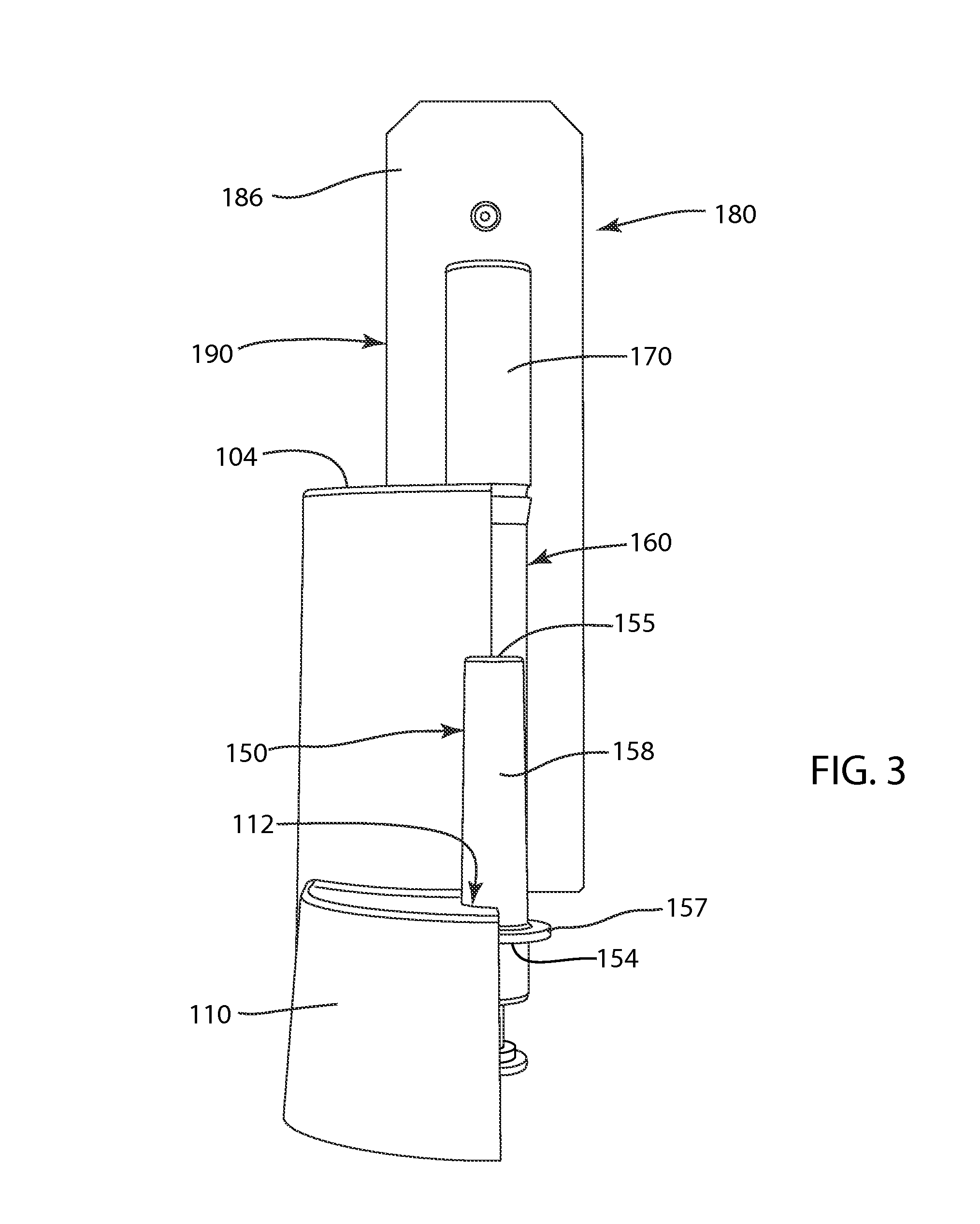
[0010]Exemplary embodiments of the present invention are related to a lateral flow immunoassay system that includes a housing that includes a base portion having a first chamber formed within an interior of the base portion and a reaction well formed within the first chamber and a body portion formed with first, second, and third openings in fluid communication with the first chamber, a vial mounted to the body portion such that the vial is in fluid communication with the first chamber via the first opening of the housing, and a sample collector comprising a stem and an absorbent retained on a distal end of the stem. The reaction well is located beneath and in fluid communication with the second and third openings. The vial is configured to dispense a buffer agent contained therein into the first chamber. The base portion is configured to, in response to the buffer agent being dispensed from the vial into the first chamber, direct the buffer agent to the reaction well. The sample collector is configured to

Problems solved by technology

Screening tests for the detection of drugs of abuse and other analytes range in complexity from very complex analytical procedures to simple immunoassay tests.
Inevitably this saves time, but as these tests are typically carried out by testing personnel who are generally not technically trained as would be a laboratory technician, the lack of professional control and the potential for incorrect interpretation of results leads to concerns that accuracy or reliability are being traded for speed.
Although the test may be simple to perform using a lateral flow device, diff

Method used


Image

  • System and Method for Lateral Flow Immunoassay Testing
  • System and Method for Lateral Flow Immunoassay Testing
  • System and Method for Lateral Flow Immunoassay Testing

Examples


Embodiment Construction

[0027]While the specification concludes with claims defining the features of the invention that are regarded as novel, it is believed that the invention will be better understood from a consideration of the description of exemplary embodiments in conjunction with the drawings. It is of course to be understood that the embodiments described herein are merely exemplary of the invention, which can be embodied in various forms. Therefore, specific structural and functional details disclosed in relation to the exemplary embodiments described herein are not to be interpreted as limiting, but merely as a representative basis for teaching one skilled in the art to variously employ the present invention in virtually any appropriate form, and it will be apparent to those skilled in the art that the present invention may be practiced without certain specific details. Further, the terms and phrases used herein are not intended to be limiting but rather to provide an understandable description o...


PUM


Abstract

A lateral flow immunoassay system is provided that includes a housing having a base portion forming a first chamber therein and a body portion formed with three openings in fluid communication with the first chamber, a vial containing a buffer agent, and a sample collector for introducing a sample fluid into the first chamber via the second opening. The vial is mounted to the housing such that a dispensing side extends into the first opening for dispensing the buffer agent therefrom into the first chamber. The housing allows the buffer agent and sample fluid to be mixed within a reaction well formed within the first chamber to form a test sample mixture. The body portion is configured to receive a receiving end of an elongated holder in the third opening and allow a test strip secured in the holder to be brought into communication with the text sample mixture.

Description

BACKGROUND OF THE INVENTION[0001]Exemplary embodiments of the present invention relate generally to point-of-care screening tests of body fluids such as saliva, blood, and other fluids for analytes including drugs of abuse and other compounds and materials. More specifically, exemplary embodiments relate screening tests for body fluids that require a test sample to be treated and incubated for a desired period of time prior to being introduced to an immunoassay test strip.[0002]The increased availability and use of drugs of abuse along with the need for testing of other analytical targets (“analytes”), for example HIV or antibodies thereto, has caused employers, governmental agencies, sports groups, hospital emergency rooms, and other organizations to utilize drug and analyte screening methods in a wide variety of situations such as in screening individuals for potential employment or purchasing insurance, or to maintain safety in the work place. Screening tests for the detection of...

Claims


Application Information

Patent Timeline
IPC IPC(8): G01N33/53
CPCG01N33/5304G01N33/54366G01N33/558G01N33/54388
Inventor CASTERLIN, DOUGLASFERRINGO, LARRYSULLIVAN, IANBERNSTINE, ROBREILLY, RICHARROYO, PABLOCIPKOWSKI, STAN
Owner HEALGEN SCI LLC
Why Eureka
Try Eureka