Monitoring system and monitoring method

a monitoring system and monitoring method technology, applied in the field of monitoring systems and monitoring methods, can solve the problems of difficult to accurately determine the person as a person, difficult to accurately determine the number of passengers boarding and deboarding, etc., and achieve the effect of high accuracy

Inactive Publication Date: 2015-09-17
PANASONIC INTELLECTUAL PROPERTY MANAGEMENT CO LTD
View PDF0 Cites 15 Cited by
  • Summary
  • Abstract
  • Description
  • Claims
  • Application Information

AI Technical Summary

Benefits of technology

[0009]According to the present invention, an image captured by a camera provided in a home is correlated with a result of counting the number of people deboarding a railway vehicle, and thus it is possible to determine the number of passengers deboarding the railway vehicle with high accuracy.

Problems solved by technology

However, in the configuration disclosed in Japanese Patent Unexamined Publication No. 2011-119912, since the television cameras are provided inside the railway vehicle, for example, in a situation in which the railway vehicle is crowded with many passengers, there is a possibility that it may be hard to accurately determine at least the number of boarding and deboarding passengers.
For example, in a situation in which the railway vehicle is crowded, in a case where a person within the imaging visual field of the television camera turns his / her back to the television camera, or an image of only the back of his / her head is captured, it may be unclear whether the person is a person (for example, a child) or baggage, and thus there is a possibility that it may be hard to accurately determine the person as a person.

Method used


Image

  • Monitoring system and monitoring method
  • Monitoring system and monitoring method
  • Monitoring system and monitoring method

Examples


first exemplary embodiment

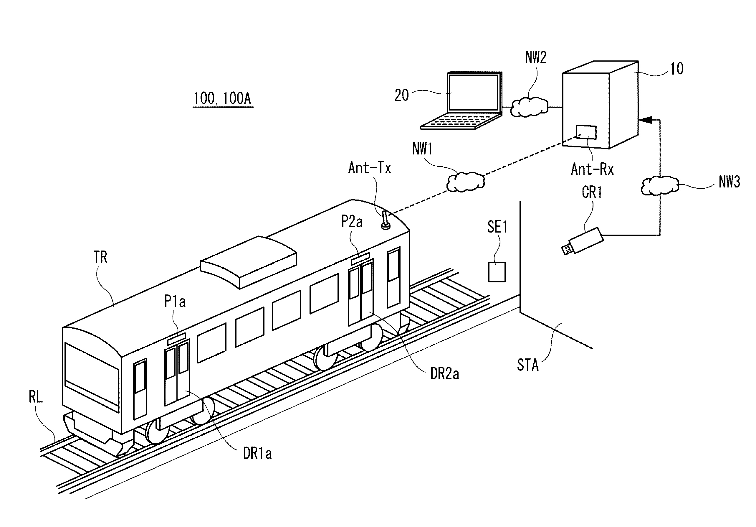
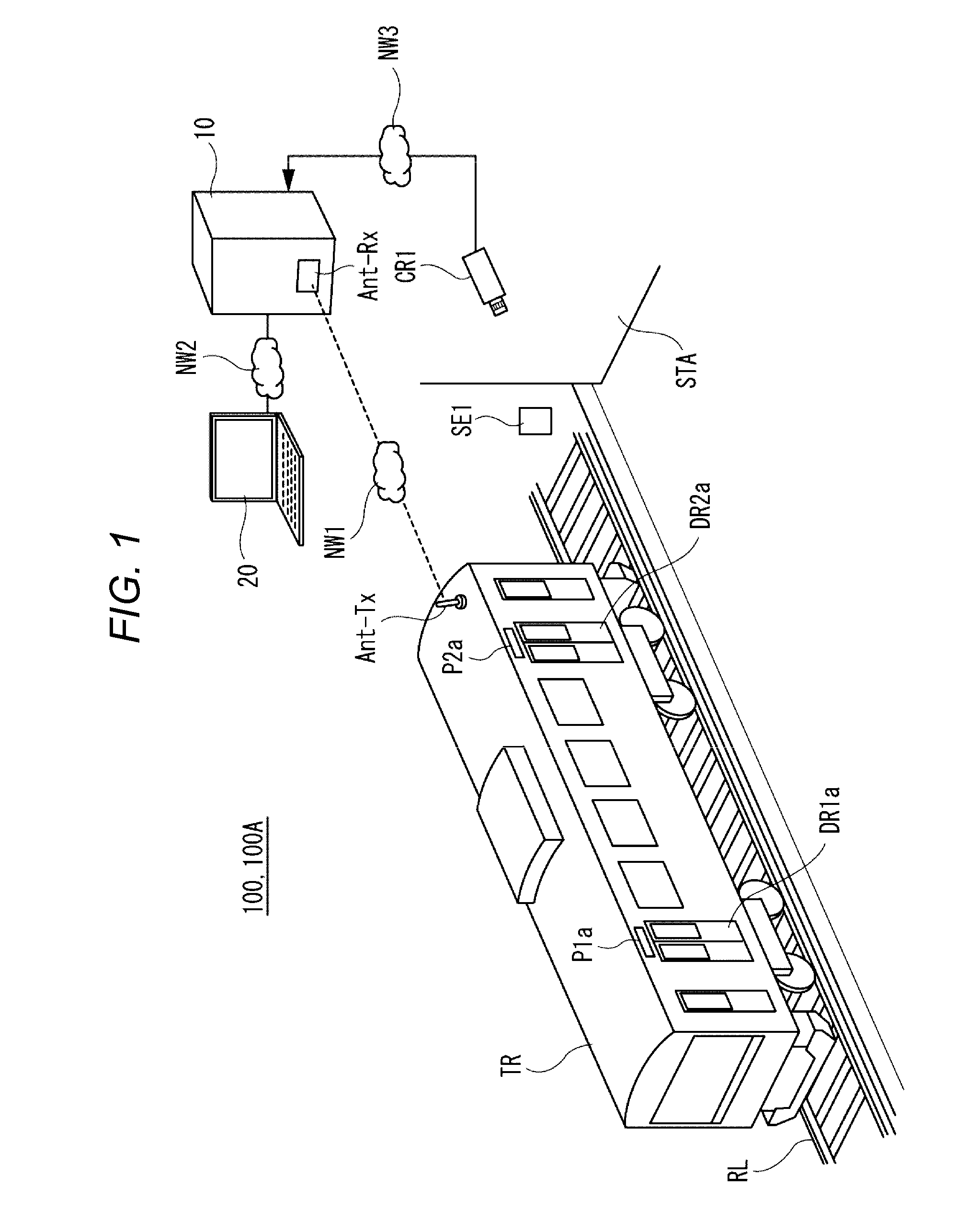
[0038]FIG. 2 is a diagram illustrating an operation summary according to a first configuration example of monitoring system 100 of the first exemplary embodiment. FIG. 3 is a diagram illustrating an operation summary according to a second configuration example of monitoring system 100 of the first exemplary embodiment. FIGS. 2 and 3 illustrate, for example, a situation in which railway vehicle TR arrives at stop STA and automatic doors DR1b, DR2b, DR3b and DR4b are ready to be opened.

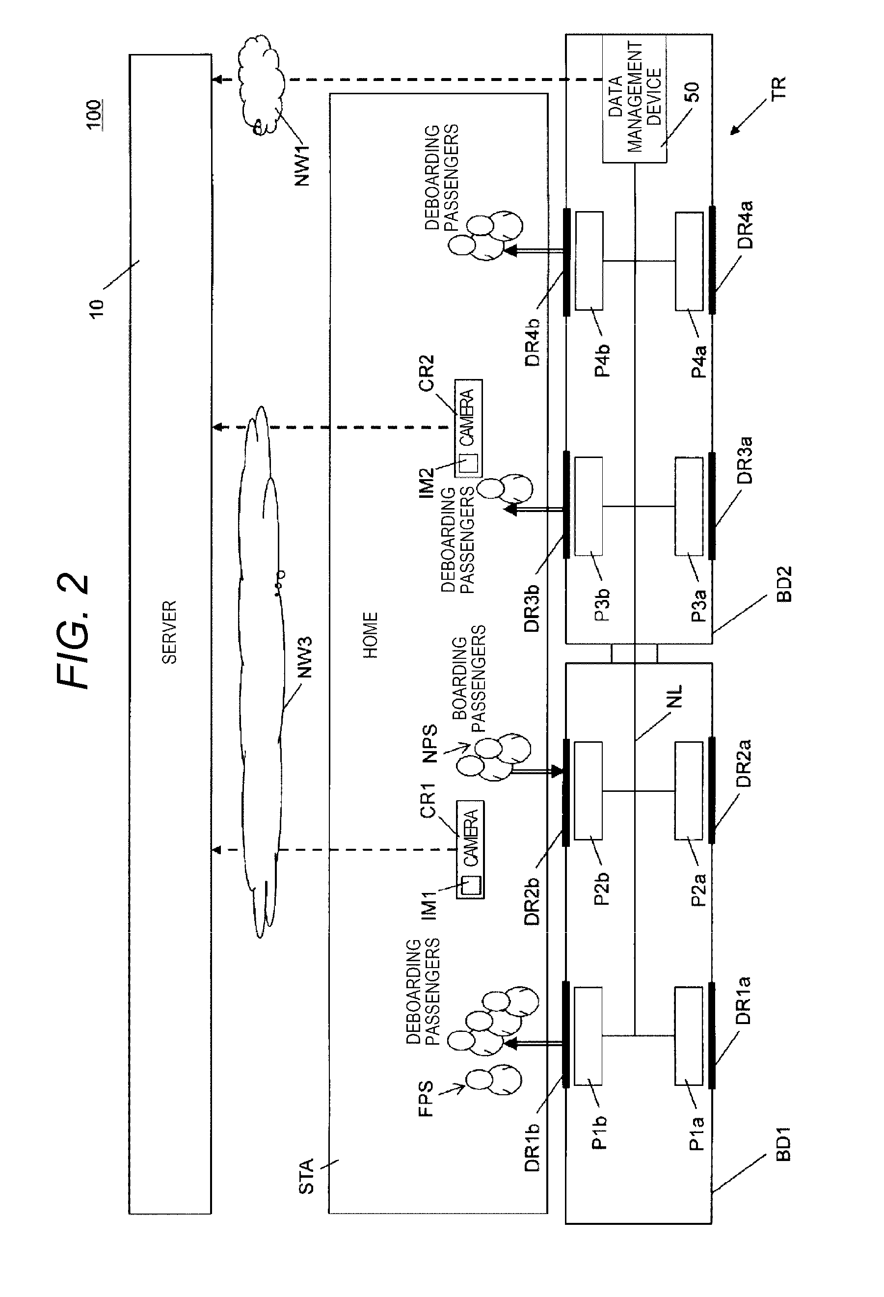
[0039]Monitoring system 100 illustrated in FIG. 2 includes number-of-people counting units P1a, P1b, P2a, P2b, P3a, P3b, P4a and P4b, data management device 50, cameras CR1 and CR2, and server 10.

[0040]Number-of-people counting units P1a, P1b, P2a, P2b, P3a, P3b, P4a and P4b are provided in railway vehicle TR, and count deboarding passengers FPS deboarding or boarding passengers NPS boarding railway vehicle TR via automatic doors DR1b, DR2b, DR3b and DR4b or automatic doors DR1a, DR2a, DR3a and DR4a, fo...

second exemplary embodiment

[0079]FIG. 8 is a diagram illustrating an operation summary of monitoring system 100A of a second exemplary embodiment. In the second exemplary embodiment, server 10A stores (accumulates) the statistically processed data regarding each of the number of deboarding people or the number of boarding people, and the video data regarding the home of stop or the video data regarding the home of the stop and the video data regarding the inside of railway vehicle TR, described in the first exemplary embodiment, and additionally stores (accumulates) delivery advertisement data which will be described later. In monitoring system 100A of the present exemplary embodiment, advertisement display devices (refer to FIGS. 9 and 11) which can display delivery advertisement data which is delivered from server 10A are provided in stops (station A, station B, and station C illustrated in FIG. 8), and advertisement display devices (refer to FIGS. 10 and 11) which can display delivery advertisement data wh...


PUM


Abstract

A monitoring system includes a number-of-people counting unit that is provided inside a railway vehicle and counts the number of deboarding passengers who deboard the railway vehicle, a first camera that is provided in a stop of the railway vehicle and captures images of deboarding passengers who deboard the railway vehicle which has arrived in a home of the stop or has arrived at the stop, and a server that stores information regarding the number of deboarding passengers counted by the number-of-people counting unit and video data regarding the deboarding passengers captured by the first camera in correlation with each other.

Description

BACKGROUND OF THE INVENTION[0001]1. Field of the Invention[0002]The present invention relates to a monitoring system and a monitoring method of monitoring the number of people deboarding a moving object such as a railway vehicle or a bus.[0003]2. Description of the Related Art[0004]As the related art in which states of an automatic door provided in a railway vehicle for passenger transport can be easily recognized on a monitor, there is an in-vehicle monitoring system disclosed in, for example, Japanese Patent Unexamined Publication No. 2011-119912.[0005]In the in-vehicle monitoring system disclosed in Japanese Patent Unexamined Publication No. 2011-119912, television cameras are provided at upper parts of automatic doors on a left side and a right side of a vehicle, and image data obtained by capturing opened / closed states of the automatic doors with the television cameras is monitored in a monitoring unit of a crew's cabin. In this in-vehicle monitoring system, the television came...

Claims


Application Information

Patent Timeline
Patent Type & Authority Applications(United States)
IPC IPC(8): G06K9/00G06Q30/02H04N7/18
CPCG06K9/00369H04N7/181G06Q30/0265G06Q30/0272G06K9/00778G07C9/00G06V20/53
Inventor YOMOGIDA, YASUOWANIGUCHI, KAZUYATAGAWA, HARUOHAGIO, MINORU
Owner PANASONIC INTELLECTUAL PROPERTY MANAGEMENT CO LTD
Why Eureka
Try Eureka