Device and method for automatically twisting metal wires, in particular for connecting adjacent, preferably mutually intersecting structure elements

a technology of automatic twisting and metal wires, which is applied in the direction of wire articles, other domestic articles, building materials handling, etc., can solve the problems of exhausting activity for the person performing the activity and also very time-consuming, and achieve the effect of shortening the formed loop

Inactive Publication Date: 2015-09-24
WOBBEN PROPERTIES GMBH
View PDF1 Cites 8 Cited by
  • Summary
  • Abstract
  • Description
  • Claims
  • Application Information

AI Technical Summary

Benefits of technology

[0014]In a preferred embodiment the apparatus according to one embodiment of the invention has a clamping device which is preferably arranged on the first or the second side of the arcuate wire guide and which is adapted to hold fast the wire passed through the first wire guide passage hole or is adapted to hold fast the wire passed through the second wire guide passage hole. In particular the clamping device is adapted to move the wire after formation of the loop beyond the twisting region of the two structural elements so that twisting by the twisting unit can be further prepared.
[0015]Further preferably the apparatus according to one embodiment of the invention has a drive means for wire conveyance, wherein the drive means is adapted to convey the wire passed through the second wire guide passage hole and held fast by the clamping device, to shorten the formed loop to a predetermined size. When the engaged wire is twisted by means of the twisting unit the spacing between the constriction produced by the twisting effect and the structural elements to be twisted becomes less with each revolution. To achieve adequate fixing of the structural elements, a certain minimum number of twists is required. In order on the other hand to use as little wire as possible, the number of twists produced should not exceed a maximum amount. For that reason it is preferable for the spacing between the twisting unit and the structural elements to be limited and defined by reducing the size of the wire loop prior to the twisting operation. It has proven to be particularly preferable to set a loop length which leaves between the twisting unit and the structural elements, an internal spacing which corresponds to the pitch dimension between the first wire guide passage hole and the second wire guide passage hole.

Problems solved by technology

As the wires to be used for the twisting operation must also have a certain stability, that activity is exhausting for the persons performing that activity and is also very time-consuming.

Method used


Image

  • Device and method for automatically twisting metal wires, in particular for connecting adjacent, preferably mutually intersecting structure elements
  • Device and method for automatically twisting metal wires, in particular for connecting adjacent, preferably mutually intersecting structure elements
  • Device and method for automatically twisting metal wires, in particular for connecting adjacent, preferably mutually intersecting structure elements

Examples


Embodiment Construction

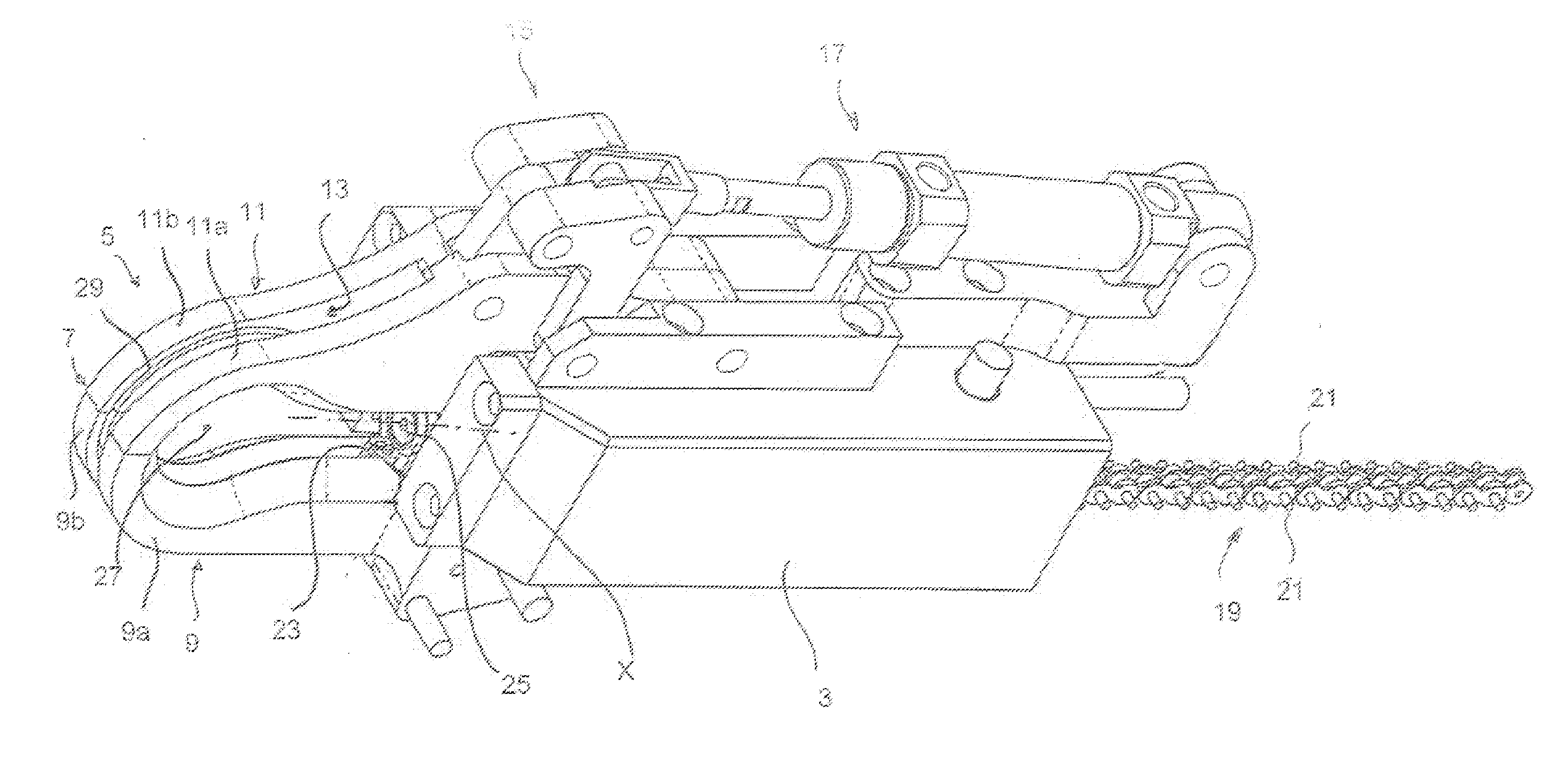
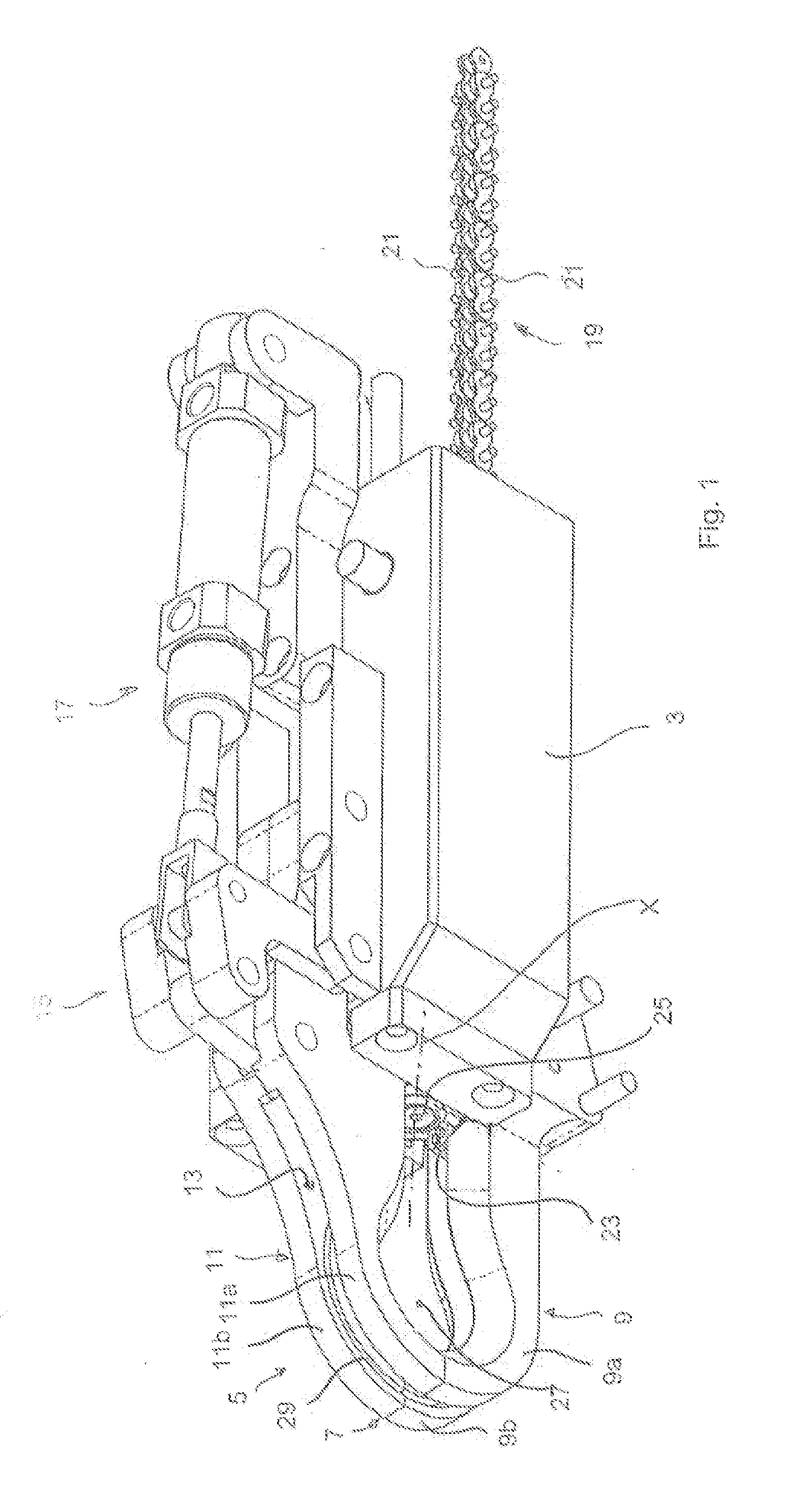
[0054]FIG. 1 shows an apparatus 1 for automatically twisting metal wires. The apparatus 1 has a main body 3. Arranged on the main body 3 at a proximal end of the apparatus 1 is an arcuate wire guide 5. The arcuate wire guide 5 has a closable and openable opening 7 arranged substantially centrally between a first side 9 of the arcuate wire guide 5 and a second side 11 of the arcuate wire guide 5.

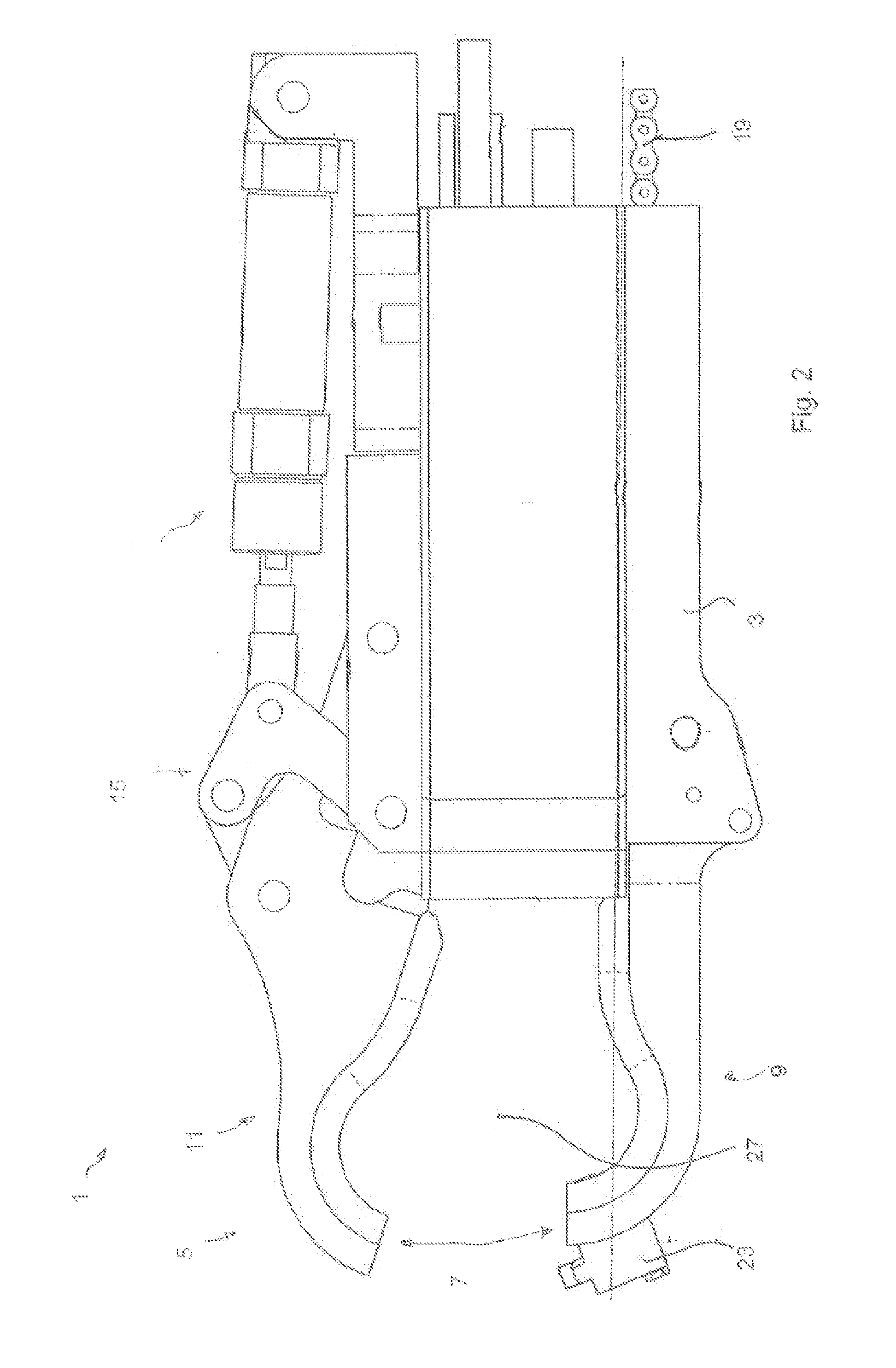
[0055]In the illustrated embodiment the first side 9 of the arcuate wire guide is arranged fixedly relative to the main body 3 while the second side 11 of the arcuate wire guide 5 can be deflected by means of a lever mechanism 15 in such a way that the opening 7 is moved from the closed position shown in FIG. 1 into an open position (FIG. 2). In the illustrated embodiment the lever mechanism 15 is driven by means of a pneumatic cylinder 17.

[0056]The arcuate wire guide 5 is of a substantially tongs-like configuration and in the interior of the two sides 9, 11 of the arcuate wire guide has a re...


PUM

PropertyMeasurementUnit
sizeaaaaaaaaaa
lattice-like structureaaaaaaaaaa
stabilityaaaaaaaaaa

Abstract

The invention concerns an apparatus, a method and a use of the apparatus for automatically twisting metal wires. The invention concerns in particular such an apparatus for connecting adjacent, preferably mutually crossing structural elements, comprising a wire feed means for feeding wire, preferably endless wire, into the apparatus, an arcuate wire guide which has a selectively openable and closable opening and which is adapted to guide the fed wire in the closed position along the arcuate wire guide from a first side of the arcuate wire guide to a second side of the arcuate wire guide, that is in opposite relationship with respect to the opening, a pulling slider adapted to engage the fed wire on the first side of the arcuate wire guide and to pull it towards the second side of the arcuate wire guide, and a twisting unit adapted to engage the fed wire on both sides of the arcuate wire guide and to twist it by means of a rotational movement.

Description

BACKGROUND[0001]1. Technical Field[0002]The present invention concerns an apparatus for automatically twisting metal wires, in particular for connecting adjacent, preferably mutually crossing structural elements. The term structural element is used in the context of this invention to denote an elongate body of a round or polygonal, for example quadrangular cross-section. Examples of such structural elements are for example tubes, bars or carriers, as are used in many respects in all fields of industry. Stranded wire bundles, so-called stranded wire cables, or prestressing cables are also viewed as being embraced by the term structural element, being used inter alia for the production of reinforcing cages for prestressed concrete components.[0003]2. Description of the Related Art[0004]A typical area of use for apparatuses of the kind set forth in the opening part of this specification is the production of such reinforcing cages, for example for prestressed concrete elements. Reinforc...

Claims


Application Information

Patent Timeline
Patent Type & Authority Applications(United States)
IPC IPC(8): B21F15/04E04G21/12
CPCE04G21/123B21F15/04
Inventor HORN, GUNTHER
Owner WOBBEN PROPERTIES GMBH
Why Eureka
Try Eureka