Machine for blowing molding articles such as containers

Active Publication Date: 2015-09-24
SERAC GROUP
View PDF5 Cites 6 Cited by
  • Summary
  • Abstract
  • Description
  • Claims
  • Application Information

AI Technical Summary

Benefits of technology

[0013]An object of the invention is to provide means suitable for increasin

Problems solved by technology

Unfortunately, in that machine, the material is present in the form of segments that alternate between being flexible and rigid, namely:
This alternation makes drivin

Method used


Image

  • Machine for blowing molding articles such as containers
  • Machine for blowing molding articles such as containers
  • Machine for blowing molding articles such as containers

Examples


Embodiment Construction

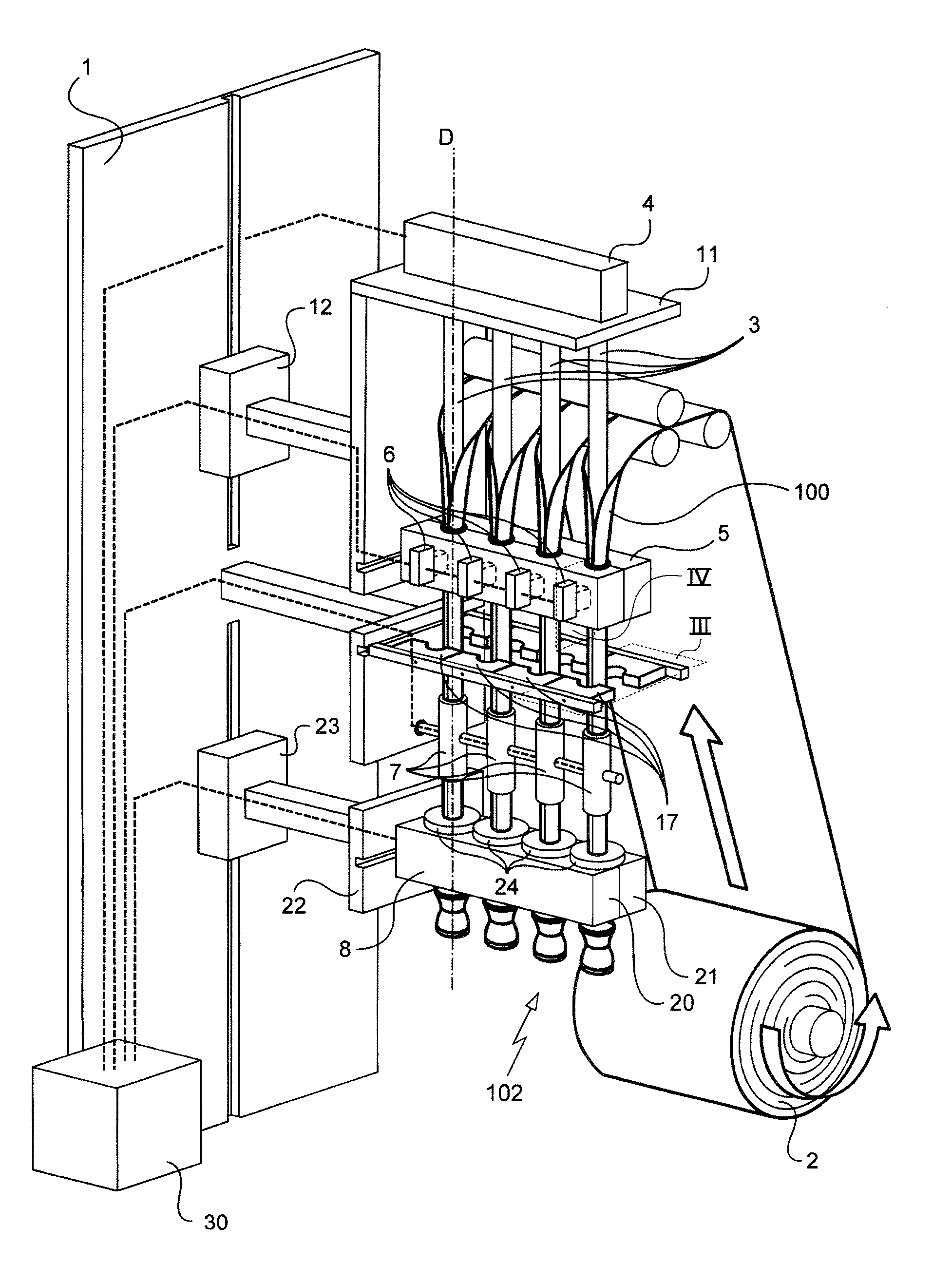
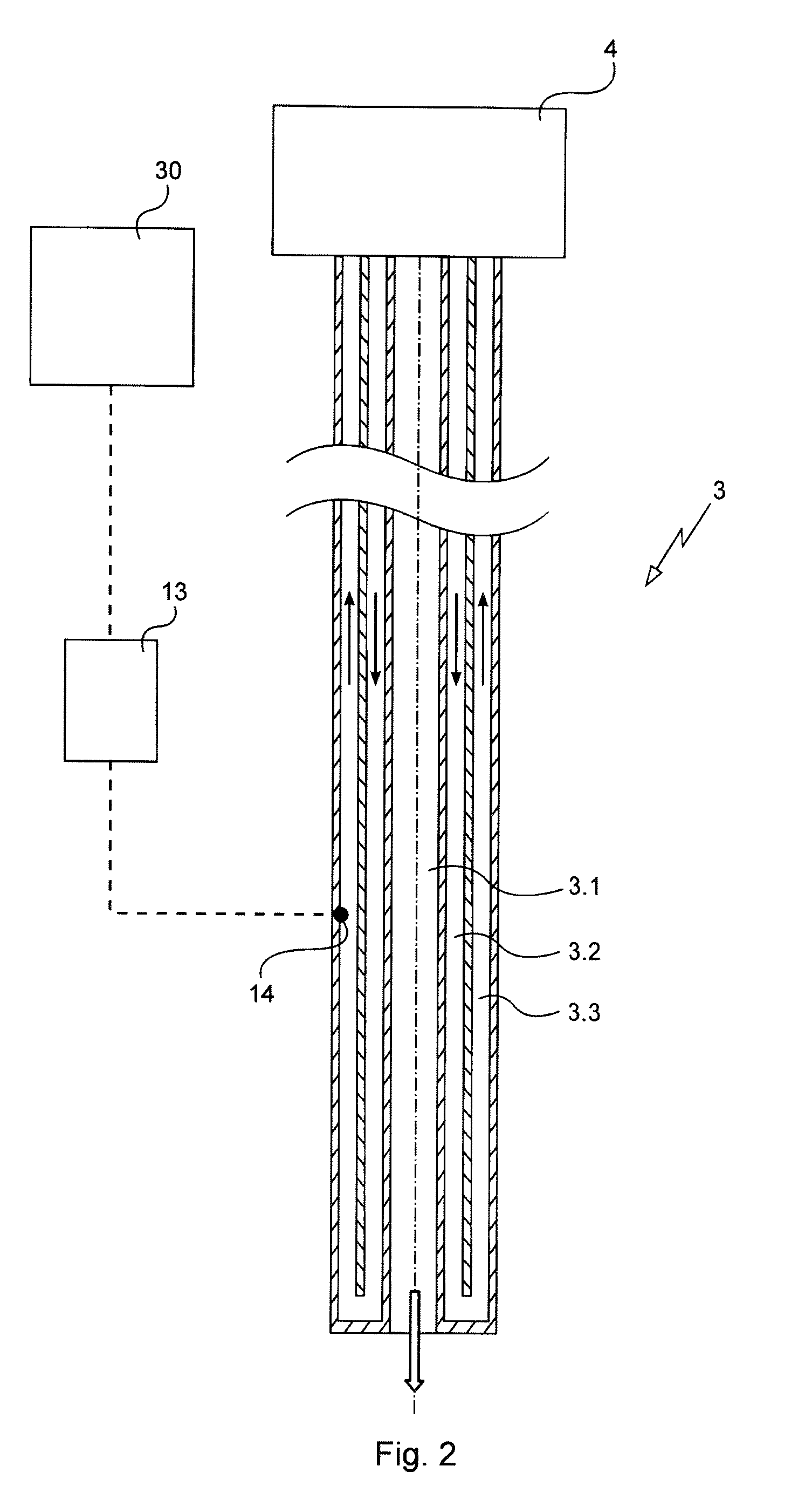
[0042]With reference to the figures, the machine of the invention is described herein in an application to fabricating containers. The machine described herein is more particularly arranged for performing the method described in Documents FR-A-2 851 227 and WO-A-2010 / 007004.

[0043]In this method, the containers are obtained by blow-molding a strip of thermoformable material.

[0044]With reference to the figures, the machine of the invention comprises a mount given overall reference 1 that is substantially in the form of a rectangular block extending in a substantially vertical direction. The mount 1 defines a path through the machine for the strip of thermoformable material 100 going from a roll 2 for unwinding a wide strip from which the strip 100 is cut out, to an outlet for containers 102 from the machine. In this example, the machine has four adjacent blow-molding units each fed with a respective strip 100 cut out from the wide strip being unwound from the roll 2.

[0045]For each blo...


PUM

PropertyMeasurementUnit
Temperatureaaaaaaaaaa
Volumeaaaaaaaaaa
Heataaaaaaaaaa

Abstract

A machine is provided for blow-molding articles from a strip of material. The machine has a mount with two frames mounted thereon. Each frame is connected to a movement actuator so as to be movable along a path of the strip between respective positions that are upstream and downstream relative to a travel direction of the strip through the machine. A pipe, a holder member, and a mold are mounted respectively on an item selected from the mount and the frames. A control unit is connected to the movement actuators to control them in such a manner as to generate a sequence of moving the guide pipe and the mold relative to the holder member and of opening and closing the mold in such a manner as to cause the strip to advance along the rectilinear path.

Description

BACKGROUND OF THE INVENTION[0001]1. Field of the Invention[0002]The present invention relates to the field of packaging, and more particularly to a machine for blow-molding articles such as containers.[0003]2. Brief Discussion of the Related Art[0004]Documents FR-A-2 851 227 and WO-A-2010 / 007004 disclose a method and a machine for blow-molding containers that are made from a strip of thermoformable material. The method is based on shaping the strip into a tube that is heated and then inserted into a mold. Air injected into the tube enables it to be deformed so as to press its wall against the inside surface of the mold cavity. That method is easier to implement than an extrusion blow-molding method and it enables a wider variety of shapes to be obtained than a conventional thermoforming method. In addition, the use of material in strip form and the limited stretching of the material make it possible to use a multilayer material.[0005]The machine described in those documents comprise...

Claims


Application Information

Patent Timeline
IPC IPC(8): B29C49/00
CPCB29C2049/0057B29C49/0047B29B11/02B29B11/04B29C49/02B29C49/4236B29C49/78B29C53/52B29C65/08B29C66/02241B29C66/1142B29C66/4312B29C66/4322B29C66/8322B29C66/851B29C49/08B29C49/60B29K2105/258B29C49/06912B29C49/48185B29C66/723B29C2049/78805B29C49/0691B29C66/022
Inventor ELEFTHERIOU, STYLIANOS
Owner SERAC GROUP
Why Eureka
Try Eureka