
Ink jet system
a jet system and jet jet technology, applied in the direction of printing, inking apparatus, other printing apparatus, etc., can solve the problems of not being able to check the flow velocity of ink, not being able to confirm the normal ink supply condition of the head, and not being able to check the flow condition of ink in the flow path, so as to reduce the number of parts and reduce costs.
- Summary
- Abstract
- Description
- Claims
- Application Information
AI Technical Summary
Benefits of technology
Problems solved by technology
Method used
Image

Examples
embodiment 1
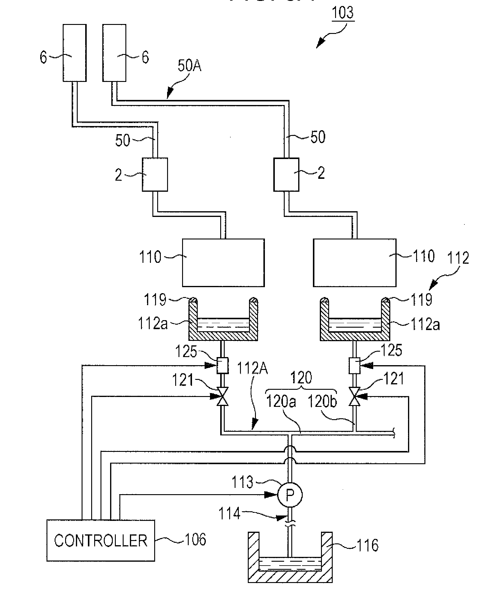
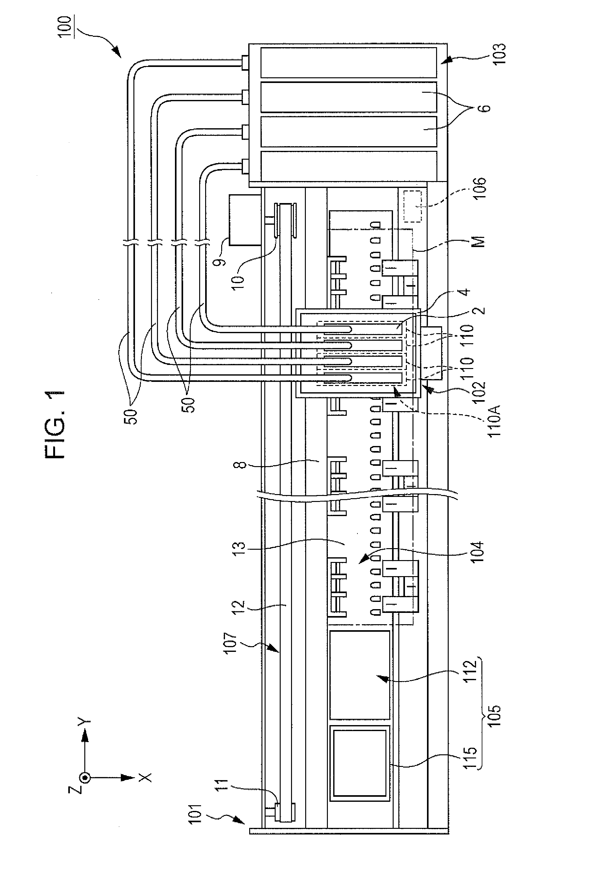
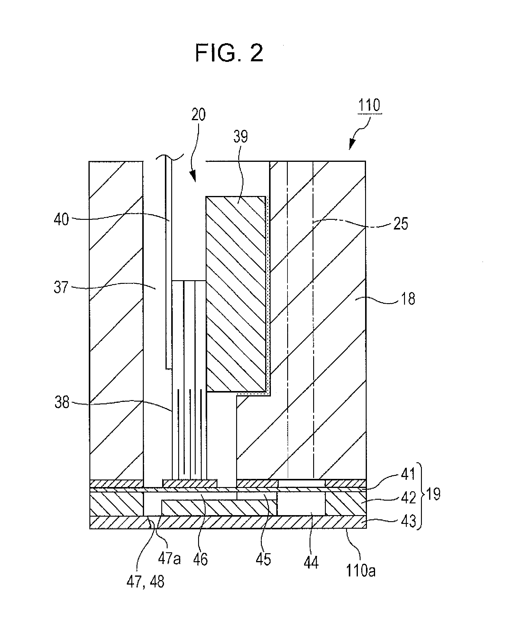
[0034]FIG. 1 is a schematic view illustrating the configuration of a printer according to Embodiment 1. A printer 100 is an apparatus which transports a medium M, such as a paper sheet and a plastic sheet, having a sheet shape and performs a printing process, as illustrated in FIG. 1. The printer 100 includes a case body 101, an ink jet mechanism 102, an ink supply mechanism 103, a medium transport mechanism 104, a maintenance mechanism (ink recovery mechanism) 105, and a controller (control portion) 106. The ink jet mechanism 102 discharges ink. The ink supply mechanism 103 supplies ink to the ink jet mechanism 102. The medium transport mechanism 104 transports the medium M. The maintenance mechanism 105 performs a maintenance operation of the ink jet mechanism 102. The controller 106 controls the mechanisms described above.
[0035]An X-Y-Z orthogonal coordinate system is used in the following description and the positional relationship between respective components will be described...
embodiment 2
[0095]Next, a cap mechanism according to Embodiment 2 will be described. A difference between this embodiment and Embodiment 1 is a sensor installation position in an ink emission path with the other configurations being the same. Accordingly, in the following description, the same reference numerals and letters are given to components or members of which the configurations are the same as those in the embodiment described above. The detailed descriptions thereof will not be repeated or will be simplified.
[0096]FIG. 5 is a view illustrating the configuration of a cap mechanism 212 according to Embodiment 2. Similarly to Embodiment 1, the cap mechanism 212 of this embodiment includes an ink emission path (the second ink path) 212A through which the ink emitted from the head 110 flows, as illustrated in FIG. 5.
[0097]In this embodiment, only one sensor 125 is disposed, in the tube 114, in a portion between the connection portion 120b and the suction mechanism 113.
[0098]Next, the operat...
embodiment 3
[0104]Next, a cap mechanism according to Embodiment 3 will be described. A difference between this embodiment and Embodiment 1 is a suction mechanism installation position in an ink emission path with the other configurations being the same. Accordingly, in the following description, the same reference numerals and letters are given to components or members of which the configurations are the same as those in the embodiment described above. The detailed descriptions thereof will not be repeated or will be simplified.
[0105]FIG. 6 is a view illustrating the configuration of a cap mechanism 312 according to Embodiment 3. Similarly to the embodiments described above, the cap mechanism 312 of this embodiment includes an ink emission path (the second ink path) 312A through which the ink emitted from the head 110 flows, as illustrated in FIG. 6.
[0106]The cap mechanism 312 of this embodiment includes a plurality of cap members 112a, a plurality of suction mechanisms 113, and a tube 214. One...
PUM
 Abstract
Description
Claims
Application Information