Composite display device
a display device and composite technology, applied in the direction of instruments, cathode-ray tube indicators, vehicle components, etc., can solve the problems of difficult to display specific display information in a state of being specially highlighted or created, and the driver is highly likely to be unaware of the display, so as to achieve a high degree of quality and improve visibility
- Summary
- Abstract
- Description
- Claims
- Application Information
AI Technical Summary
Benefits of technology
Problems solved by technology
Method used
Image

Examples
first embodiment
Appearance of Device
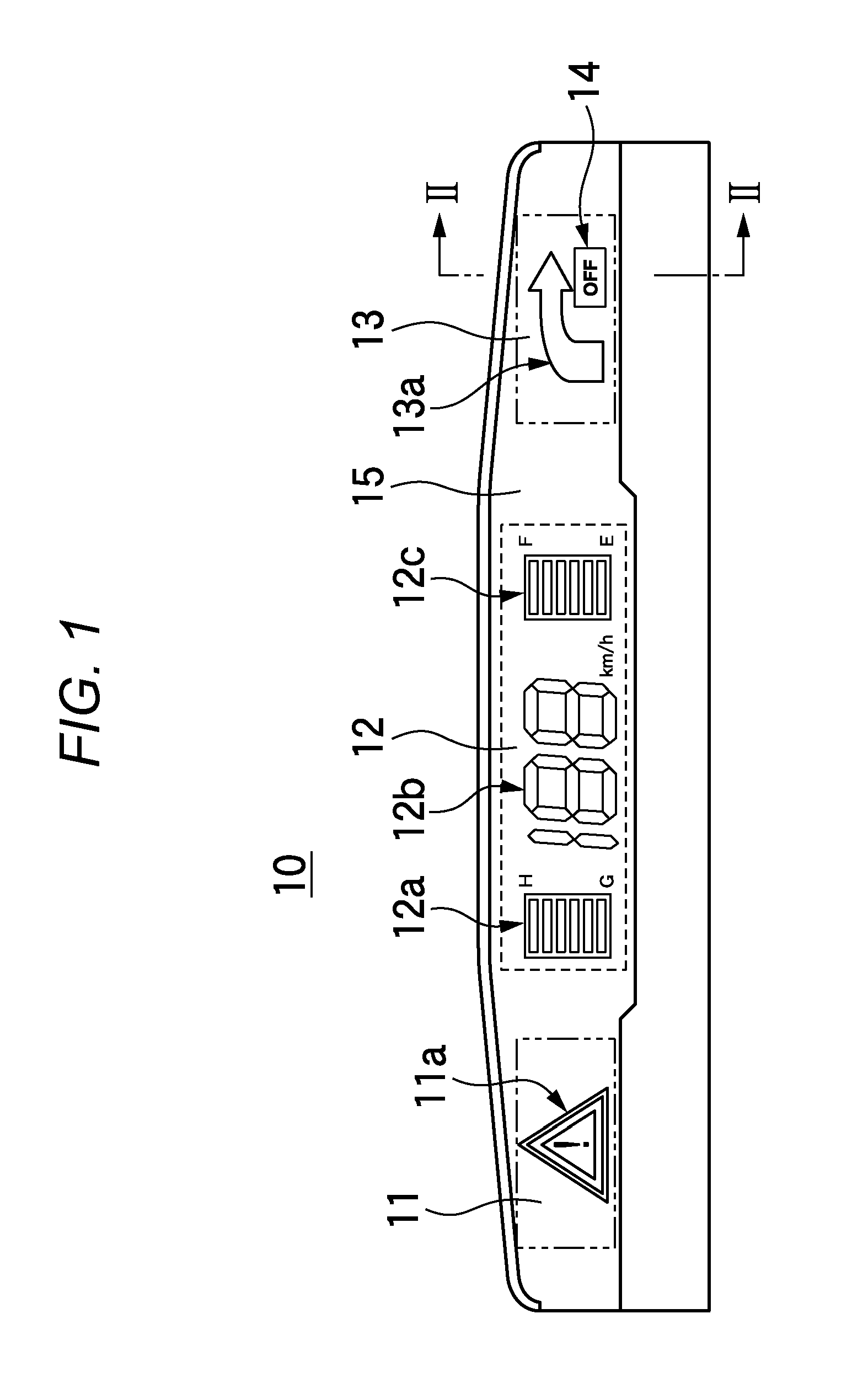
[0041]A specific example of an appearance of a meter unit 10 is illustrated in FIG. 1. The meter unit 10 is, as a vehicle onboard unit, built in a vehicle such as an automobile. That is, the meter unit 10 is installed at a position of a dash board which is positioned in front of a driver's seat in the vehicle in order to display information required for the driver to drive a vehicle and transmit the information to a driver.
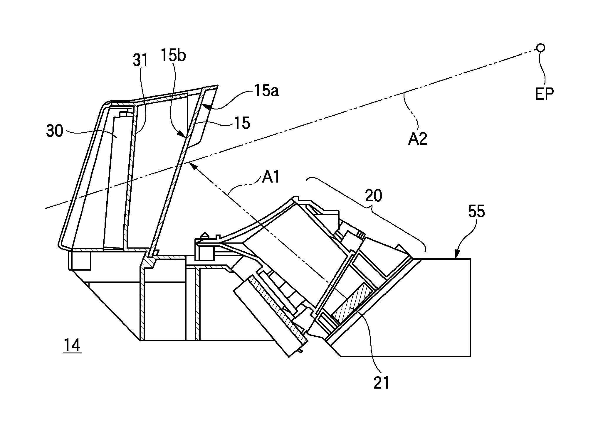
[0042]The meter unit 10 illustrated in FIG. 1 is roughly divided into four display units. That is, a left side display unit 11, a central display unit 12, a right side display unit 13, and a composite display unit 14 are provided in the meter unit 10. In addition, a combiner 15 is installed in a front surface of the meter unit 10 (a position closer to a driver than a display part). The combiner 15 is an optical member, and can synthesize a plurality of optical images by the combination of reflection and transmission of light.
[0043]The left side...
modification example
Description of Modification Example
[0099]Modification Example (1) of the operation which is illustrated in FIG. 6 is illustrated in FIG. 7. In the operation illustrated in FIG. 7, steps S13B and S14B are added instead of steps S13 and S14 in FIG. 6.
[0100]In step S13B of FIG. 7, the electronic control unit ECU specifies the data to be displayed and the display positions P1 and P2 as in S13, and further specifies display size S1 and display size S2 and display brightness B1 and display brightness B2.
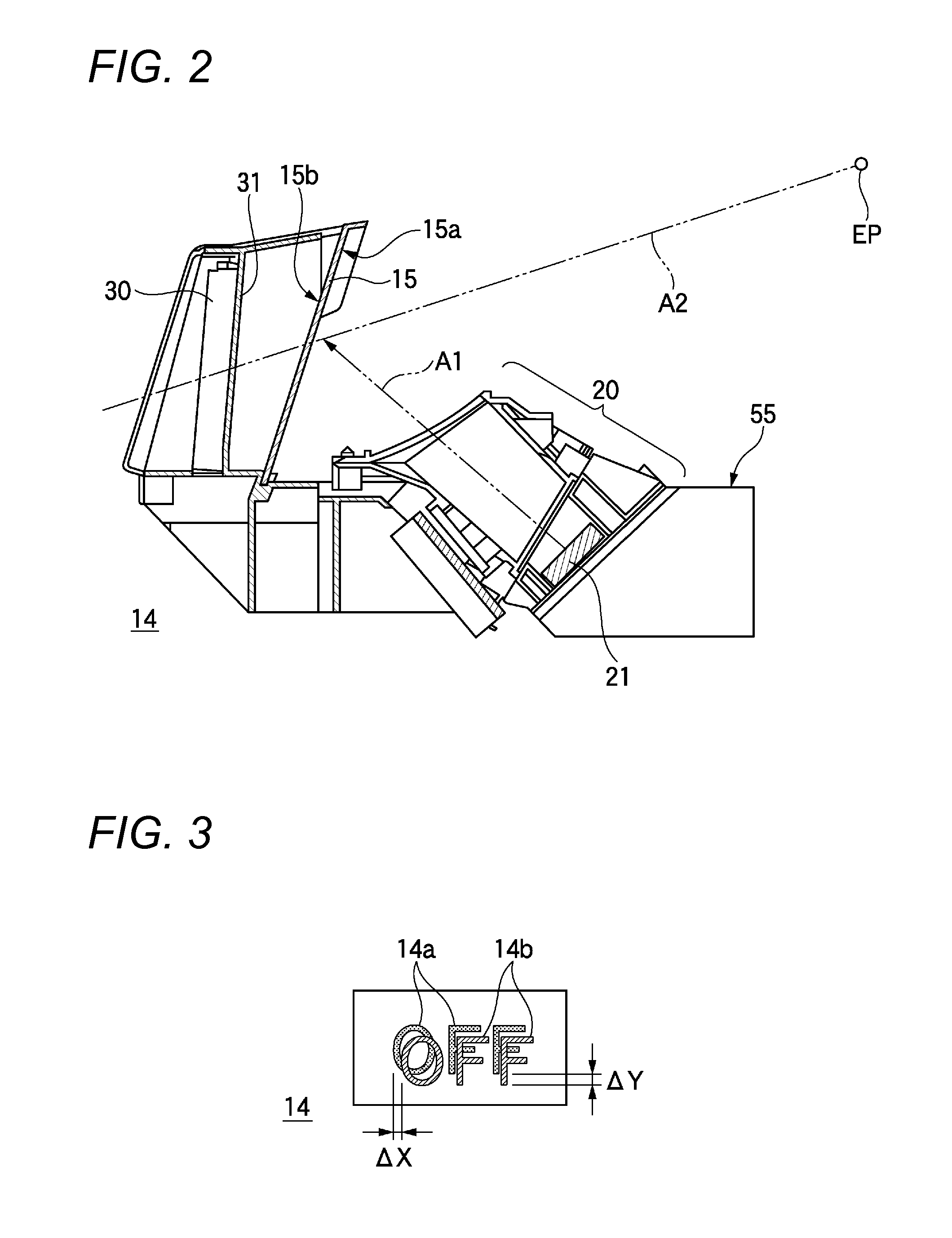
[0101]Here, the display size S1 corresponds to, for example, the size (the size of the pattern such as the text) of the visual information which is displayed by the virtual image projection unit 20 as the virtual image display 14b illustrated in FIG. 3, and the display size S2 corresponds to the size of the visual information which is displayed by the real image display unit 30 as the real image display 14a. In addition, the display brightness B1 represents the brightness of the visual inf...
second embodiment
Description of Appearance
[0104]A specific example of an appearance of a meter unit 10B of the present embodiment is illustrated in FIG. 8. The meter unit 10B illustrated in FIG. 8 is a modification example of the meter unit 10 illustrated in FIG. 1, and is provided with the left side display unit 11, a central display unit 12B, and a right side display unit 13B. In addition, a portion of the right side display unit 13B can be displayed by being overlapped with the real image and the virtual image which is the same as those of the aforementioned composite display unit 14.
[0105]In addition, the central display unit 12B in FIG. 8 includes a cooperative display unit 12d, and the right side display unit 13B includes a cooperative display unit 13b. In the present embodiment, the cooperative display unit 12d and the cooperative display unit 13b which are disposed at mutually distant positions are used to display the same situation or used to display the situation of greater relevance to ea...
PUM
 Abstract
Description
Claims
Application Information
 - R&D
- Intellectual Property
- Life Sciences
- Materials
- Tech Scout
- Unparalleled Data Quality
- Higher Quality Content
- 60% Fewer Hallucinations
Browse by: Latest US Patents, China's latest patents, Technical Efficacy Thesaurus, Application Domain, Technology Topic, Popular Technical Reports.
© 2025 PatSnap. All rights reserved.Legal|Privacy policy|Modern Slavery Act Transparency Statement|Sitemap|About US| Contact US: help@patsnap.com