Power supply device and image forming apparatus

Active Publication Date: 2015-09-24
CANON KK
View PDF3 Cites 2 Cited by
  • Summary
  • Abstract
  • Description
  • Claims
  • Application Information

AI Technical Summary

Benefits of technology

[0009]According to aspects of the present invention, the size and cost of a power su

Problems solved by technology

As a result of provision of a large number of compon

Method used


Image

  • Power supply device and image forming apparatus
  • Power supply device and image forming apparatus
  • Power supply device and image forming apparatus

Examples


Example

First Embodiment

(1) Configuration of Image Forming Apparatus

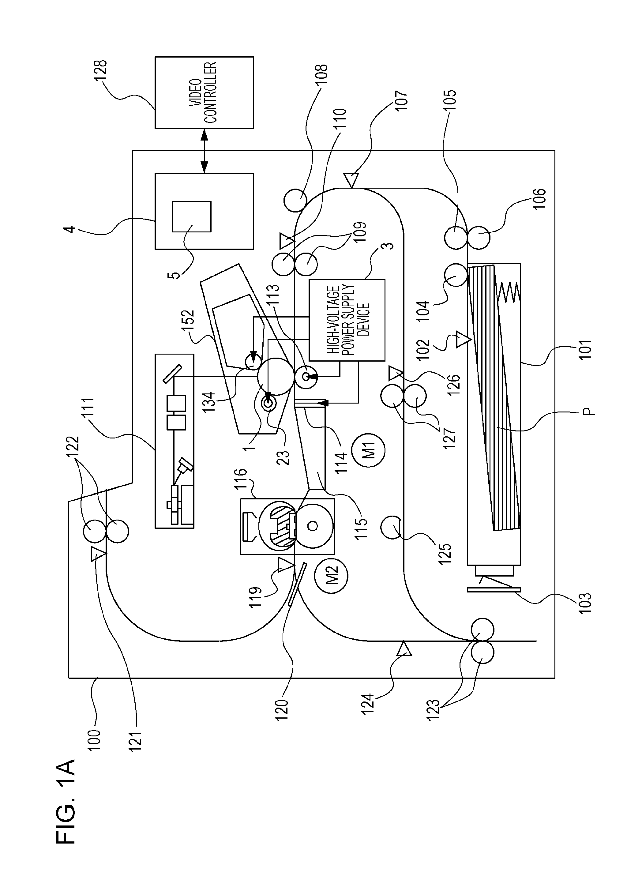
[0021]FIG. 1A is a diagram illustrating the configuration of an image forming apparatus 100 according to a first embodiment. The image forming apparatus 100 includes a deck 101, which is a storage unit that stores a recording material P, which is recording sheets. The image forming apparatus 100 also includes a paper presence sensor 102 that detects presence or absence of the recording material P in the deck 101 and a paper size detection sensor 103 that detects the size of the recording material P in the deck 101. The image forming apparatus 100 also includes a pickup roller 104 that feeds the recording material P to a conveying path from the deck 101 and a feed roller 105 that conveys the recording material P fed by the pickup roller 104. The image forming apparatus 100 also includes a retard roller 106 that faces the feed roller 105 and that prevents simultaneous feeding of a plurality of sheets. The image forming appara...

Example

Second Embodiment

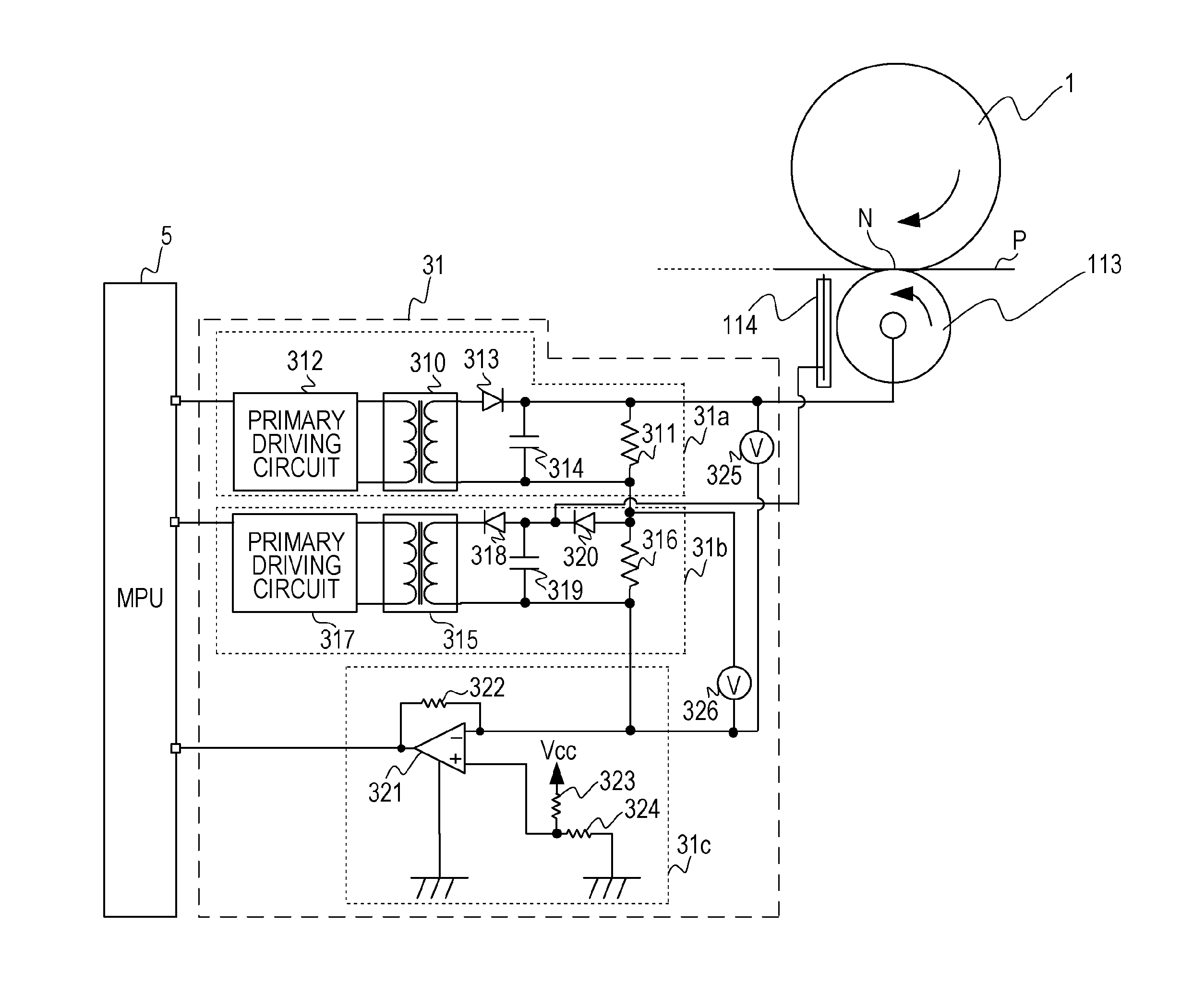
[0043]FIG. 5 is a flowchart according to the second embodiment. In the first embodiment, current flowing from the positive high-voltage circuit 31a is detected with the negative high-voltage circuit 31b in the off state. On the other hand, in this embodiment, even if both the positive high-voltage circuit 31a and the negative high-voltage circuit 31b are in the on state, a desired current can flow as the transfer positive voltage having a positive polarity. Differences from the first embodiment will be described with reference to FIGS. 3A and 3B. For example, the neutralizing voltage may or may not be applied to the neutralizing pins 114 depending on an environment, the type of sheet, and printing speed. If the neutralizing voltage is applied to the neutralizing pins 114, the transfer positive voltage having a positive polarity is applied to the transfer roller 113 in order to transfer a toner image on the photosensitive drum 1 onto the recording material P. Next, t...

Example

Third Embodiment

(1) Configuration of Image Forming Apparatus and Transfer Unit

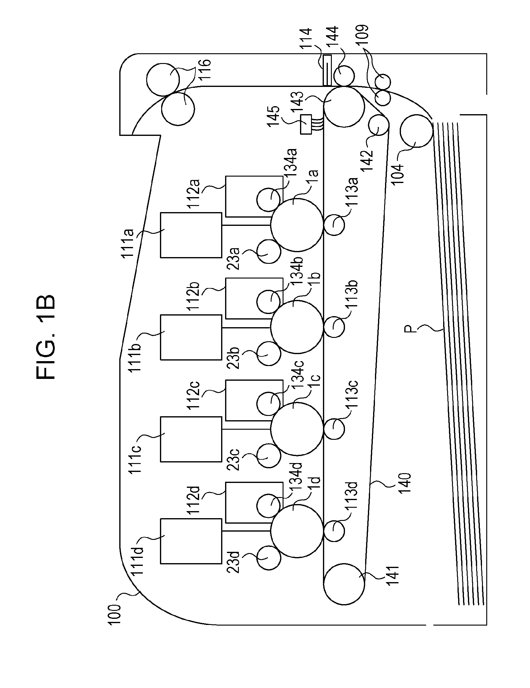
[0049]FIG. 1B is a schematic diagram illustrating the configuration of an image forming apparatus 100 according to a third embodiment. In FIG. 1B, the same components as those according to the first embodiment illustrated in FIG. 1A are given the same reference numerals, and accordingly description of the operations thereof is omitted. One of major differences between this embodiment illustrated in FIG. 1B and the first embodiment illustrated in FIG. 1A is that a plurality of image bearing members (photosensitive drums) and an intermediate transfer member (intermediate transfer belt) are included in this embodiment. The image forming apparatus 100 illustrated in FIG. 1B includes the same number of (for example, four) image forming units as the number of colors. In FIG. 1B, the reference numerals of the image forming units are given additional letters, namely a, b, c, and d, respectively. The additional let...


PUM


Abstract

An imaging forming apparatus includes a positive high-voltage circuit that generates voltage having a positive polarity, a negative high-voltage circuit connected in series with the positive high-voltage circuit and generates voltage having a negative polarity, a transfer roller to which the voltage generated by the positive high-voltage circuit or the negative high-voltage circuit is supplied, neutralizing pins to which the voltage generated by the negative high-voltage circuit is supplied, a current detection circuit that detects current flowing into the transfer roller, and a diode connected between the transfer roller and the neutralizing pins and that separates a path for the current flowing into the transfer roller and a path for current flowing into the neutralizing pins from each other.

Description

BACKGROUND[0001]1. Field[0002]Aspects of the present invention generally relate to a power supply device and an image forming apparatus.[0003]2. Description of the Related Art[0004]An image forming apparatus adopting an electrophotographic method includes a high-voltage power supply device, which is essential to a process for forming an image on a recording material. As the high-voltage power supply device, for example, one of various modular power supplies such as a charging high-voltage power supply, a developing high-voltage power supply, and a transfer high-voltage power supply is used. These power supplies have different specifications in accordance with the configuration of the image forming apparatus. For example, voltage of an alternating-current high-voltage power supply is superimposed upon voltage of a direct-current high-voltage power supply, or voltage of a direct-current positive high-voltage power supply is superimposed upon voltage of a direct-current negative high-v...

Claims


Application Information

Patent Timeline
IPC IPC(8): G03G15/16G03G15/00H02M7/06
CPCH02M7/06G03G15/80H02M3/33561H02M1/0009H02M1/0077
Inventor MINOBE, TARO
Owner CANON KK
Why Eureka
Try Eureka