Light-emitting element drive circuit

a technology of drive circuit and light-emitting element, which is applied in the direction of instruments, semiconductor lasers, static indicating devices, etc., can solve the problems of poor yield, difficult to maintain stable oscillation output, and high percentage of optical transmission system cost, and achieve good light-emitting characteristics

Active Publication Date: 2005-11-15
NXP USA INC
View PDF4 Cites 27 Cited by
  • Summary
  • Abstract
  • Description
  • Claims
  • Application Information

AI Technical Summary

Benefits of technology

[0018]According to the invention described in claim 5, the laser diode can attain a good light-emitting characteristic and according to the invention described in claim 6, the photodiode can generate a monitor current that is in proportion to the amount of light received.

Problems solved by technology

The laser diode, which suffers poor yields due to manufacturing variations, accounts for a rather high percentage of the cost of the optical transmission system.
In a laser diode, it is difficult to maintain stable oscillation output because of fluctuations in characteristics based on manufacturing variations, changes in temperature characteristics of the laser diode, and changes over time (aging).
However, with the aforedescribed automatic power control (APC) circuit, control cannot be achieved in consideration of changes in the threshold current Ith.
As a result, changes in the threshold current Ith cannot be detected, so that the bias current Ib and light-emitting current Ip cannot be controlled in consideration of changes in the threshold current Ith.

Method used


Image

  • Light-emitting element drive circuit
  • Light-emitting element drive circuit
  • Light-emitting element drive circuit

Examples


Embodiment Construction

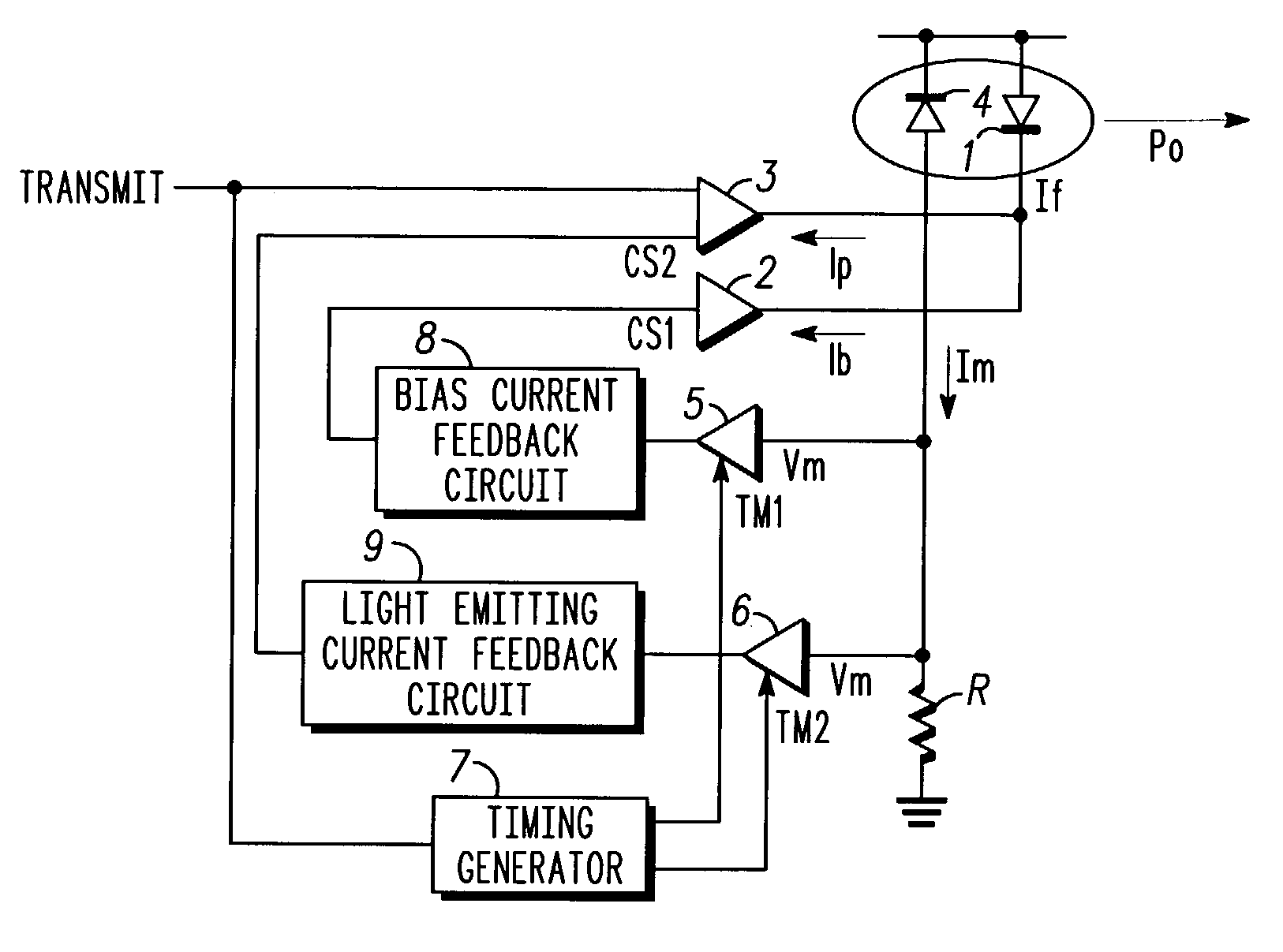
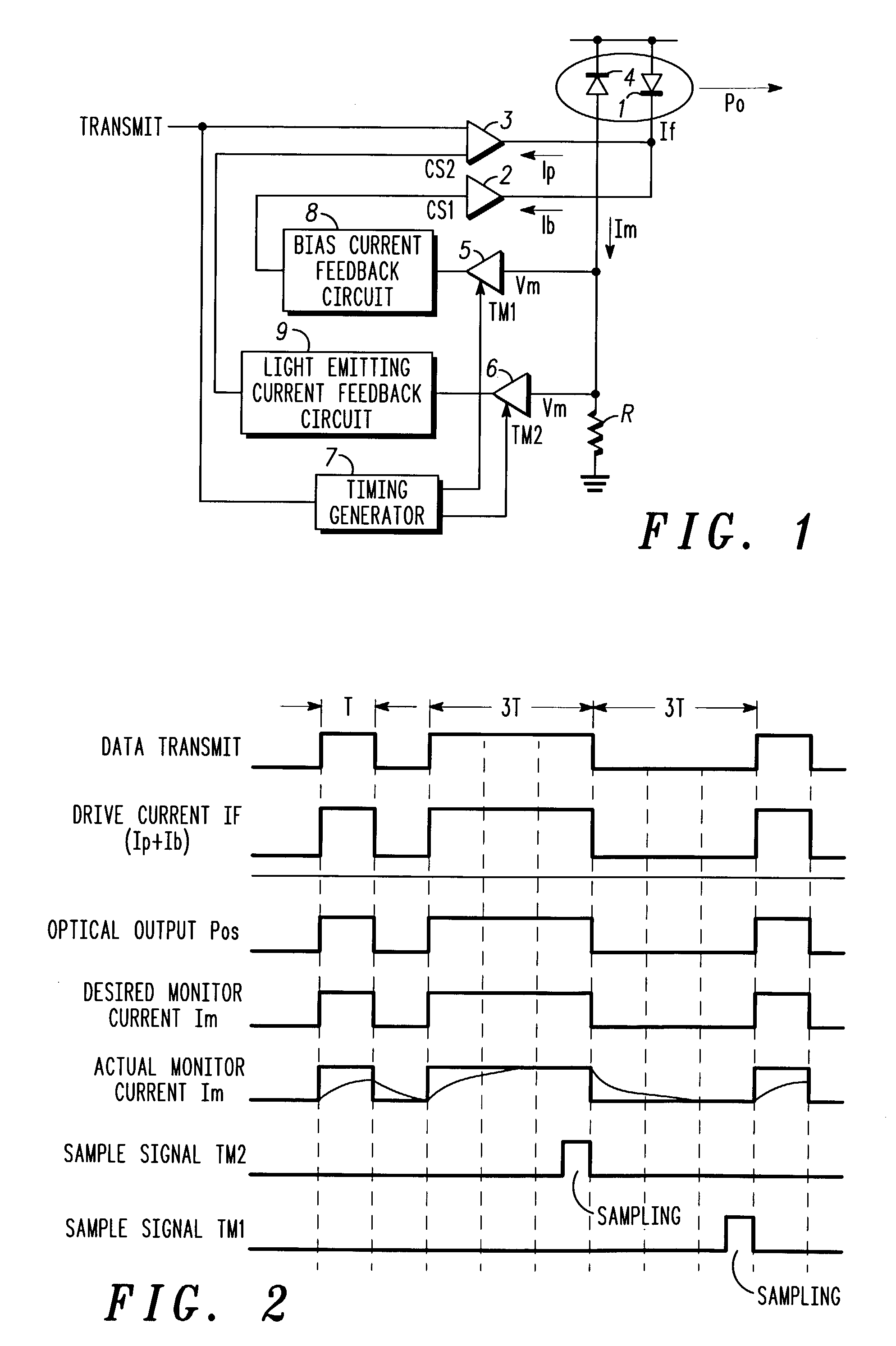
[0023]One embodiment of a laser diode drive circuit that embodies a light-emitting element drive circuit of the present invention is described in detail below with reference to FIGS. 1 and 2.

[0024]FIG. 1 is an electrical block circuit diagram of a laser diode drive circuit. FIG. 2 is an operational timing diagram for each component circuit of the laser diode drive circuit. In FIG. 1, a laser diode 1 that acts as a light-emitting element is supplied with a drive current If that is a combination of a bias current Ib output from a bias current drive circuit 2 and a light-emitting current Ip output from a data current drive circuit 3. The bias current drive circuit 2 acts as a first drive current generation circuit and outputs the bias current Ib having an identical value to the current (threshold current Ith) where the laser diode 1 starts to emit light. The data current drive circuit 3 that acts as a second drive current generation circuit outputs the light-emitting current Ip that ca...


PUM


Abstract

A light-emitting element drive circuit capable of controlling the drive current of a light-emitting element in consideration of changes in a threshold value of the light-emitting element. A laser diode 1 emits light in accordance with a bias current Ib of a bias current drive circuit 2 and a light-emitting current Ip of a data current drive circuit 3. A photodiode 4 outputs a monitor current Im that corresponds to the optical output of the laser diode 1. A bias current feedback circuit 8 detects a change in the threshold current in accordance with the current Im, and outputs a control signal CS1. The bias current drive circuit 2 generates a bias current Ib that corresponds to the threshold current Ith of the laser diode 1 after the change. A light-emitting current feedback circuit 9 detects a change in the optical output of the laser diode 1 in accordance with the current Im, and outputs a controls signal CS2. The data current drive circuit 3 generates a light-emitting current Ip relative to a pre-determined optical output of the laser diode 1 in accordance with the control signal CS2.

Description

BACKGROUND OF THE INVENTION[0001]The present invention relates to light-emitting element drive circuits, and more particularly to a drive circuit suitable as a laser diode drive circuit.[0002]A laser diode is a major component of an optical transmission system. The laser diode, which suffers poor yields due to manufacturing variations, accounts for a rather high percentage of the cost of the optical transmission system.[0003]In a laser diode, it is difficult to maintain stable oscillation output because of fluctuations in characteristics based on manufacturing variations, changes in temperature characteristics of the laser diode, and changes over time (aging). Thus, to compensate for such variations, the laser diode typically has its drive current (forward current), If, controlled by an automatic power control (APC) circuit.[0004]FIG. 3 is an electrical block circuit diagram of an automatic power control (APC) circuit. In FIG. 3, a laser diode 1 is supplied a drive current If that c...

Claims


Application Information

Patent Timeline
Patent Type & Authority Patents(United States)
IPC IPC(8): H01S5/00H01S5/042H01S5/0683H04B10/07H04B10/40H04B10/50H04B10/564H04B10/60H04B10/67H04B10/69
CPCH01S5/042
Inventor SAKAMOTO, HIROSHIHOSHI, TSUKASA
Owner NXP USA INC
Why Eureka
Try Eureka