Inorganic thin film electroluminescent device and method for manufacturing the same

Active Publication Date: 2005-03-24
ELECTRONICS & TELECOMM RES INST
View PDF9 Cites 28 Cited by
  • Summary
  • Abstract
  • Description
  • Claims
  • Application Information

AI Technical Summary

Benefits of technology

[0009] The present invention is contrived to solve the aforementioned problems, and is directed to an inorganic thin film electroluminescent dev

Problems solved by technology

While the inorganic thin film electroluminescent device has merits of high brightness, long life time, high resolving power, or the like, it has demerits of high driving voltage and a lack of a stable blue phosphor.
However, there was a problem from the point of view of a device stability, and

Method used


Image

  • Inorganic thin film electroluminescent device and method for manufacturing the same
  • Inorganic thin film electroluminescent device and method for manufacturing the same
  • Inorganic thin film electroluminescent device and method for manufacturing the same

Examples


Example

[0022] The present invention will be described in detail by way of a preferred embodiment with reference to accompanying drawings, in which like reference numerals are used to identify the same or similar parts.

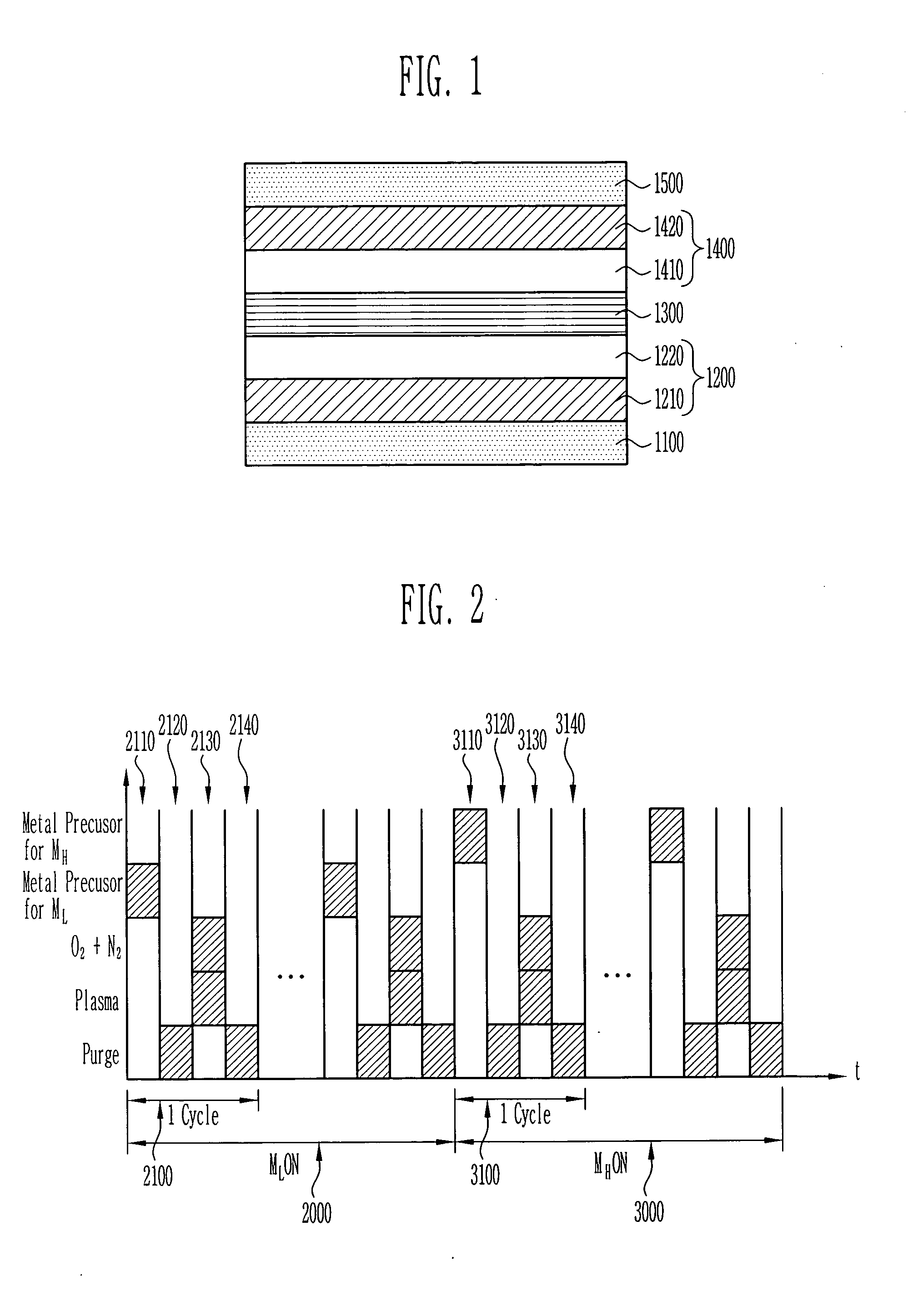
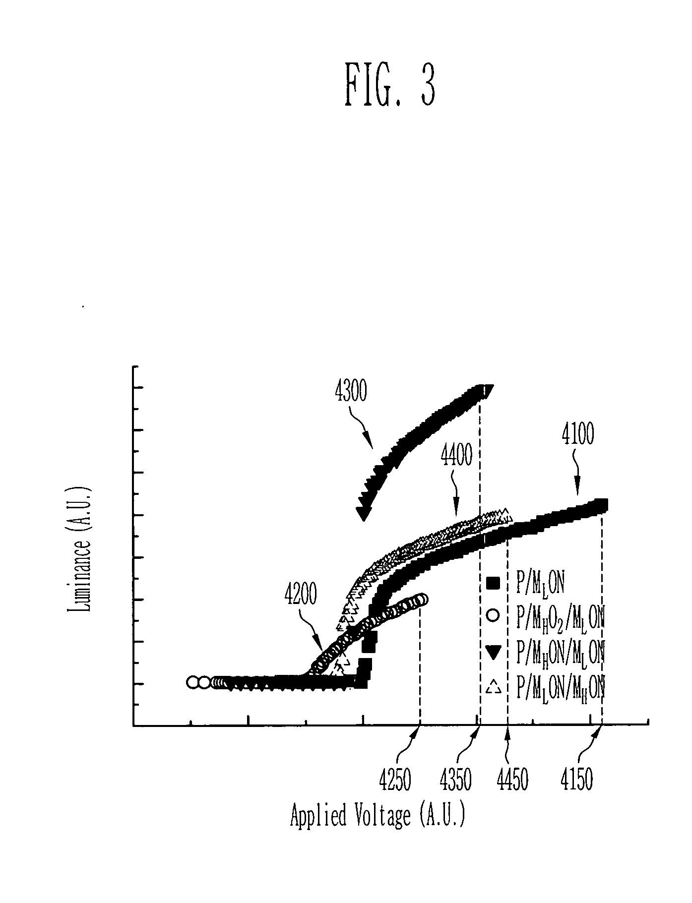
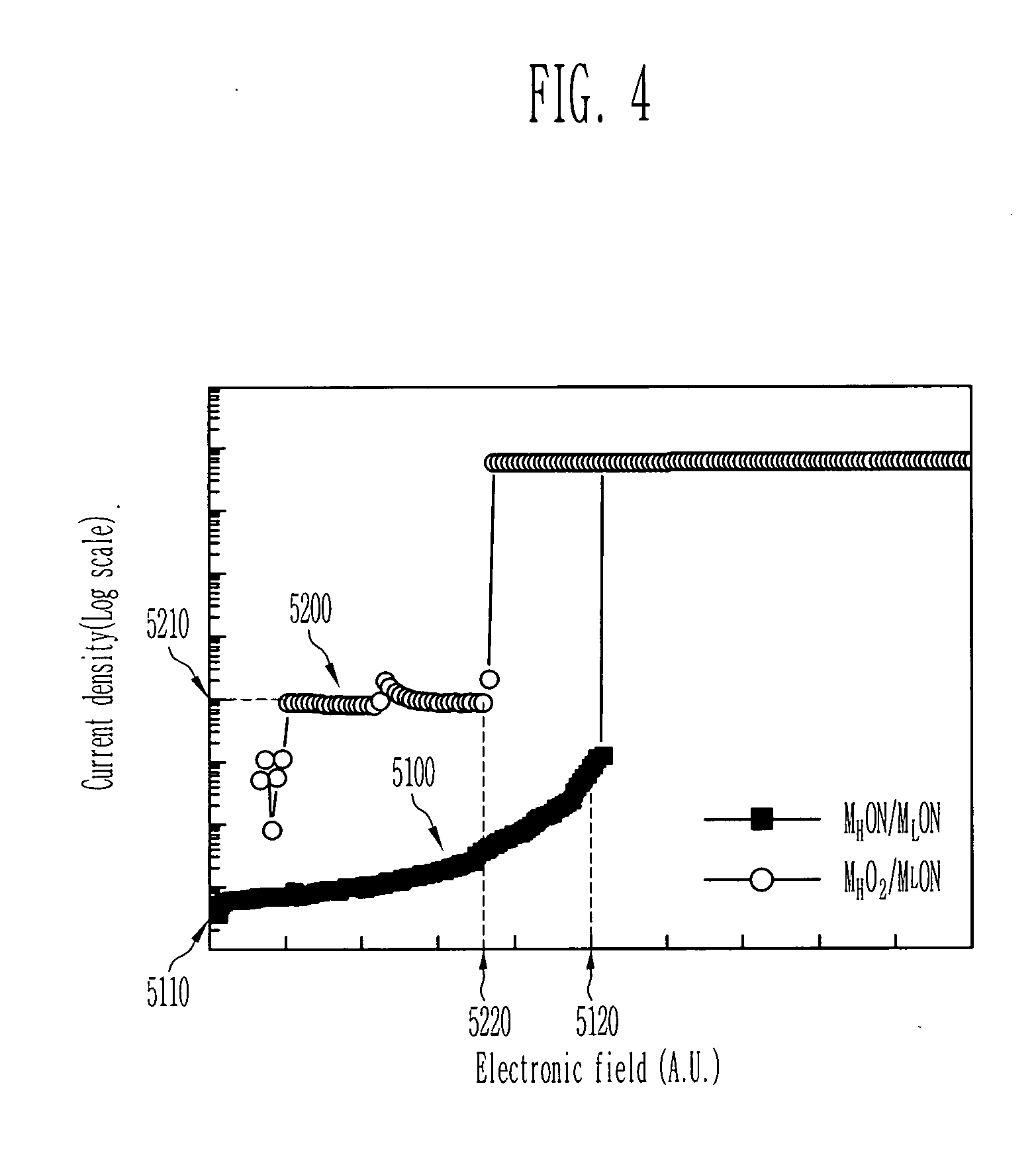
[0023]FIG. 1 shows a schematic structure of an inorganic thin film electroluminescent device, according to a preferred embodiment of the present invention.

[0024] The inorganic thin film electroluminescent device of FIG. 1 comprises a lower electrode 1100, a lower insulating layer 1200, a phosphor 1300, an upper insulating layer 1400, and an upper electrode 1500.

[0025] The lower electrode 1100 and the upper electrode 1500 may be an indium tin oxide (ITO) of a transparent electrode having hundreds of nm in a thickness.

[0026] The phosphor 1300 can be formed by depositing a sulfide such as a zinc sulfide (ZnS), a strontium sulfide (SrS), etc. with a dopant together. Here, the dopant may be a manganese (Mn), a lead (Pb), a lanthanide, etc. that provides luminescent colors of t...


PUM

PropertyMeasurementUnit
Ratioaaaaaaaaaa

Abstract

Provided is an inorganic thin film electroluminescent device including a lower electrode, a lower insulating layer, a phosphor, an upper insulating layer, and an upper electrode, and the method for manufacturing the same, whereby it is possible to obtain the inorganic thin film electroluminescent device capable of realizing high brightness, excellent luminescence efficiency, and low breakdown field.

Description

BACKGROUND [0001] 1. Field of the Invention [0002] The present invention relates to an inorganic thin film electroluminescent device and a method for manufacturing the same and, more specifically, to an inorganic thin film electroluminescent device having a multi-layered insulating layer and a method for manufacturing the same. [0003] 2. Discussion of Related Art [0004] An inorganic thin film electroluminescent device is such a device that an electron accelerated by high electric field collides with a phosphor to excite it, thereby inducing luminescence. While the inorganic thin film electroluminescent device has merits of high brightness, long life time, high resolving power, or the like, it has demerits of high driving voltage and a lack of a stable blue phosphor. It has been disclosed in “Journal of Applied Physics, 71, pp 1509, 1992”. [0005] Meanwhile, the inorganic thin film electroluminescent device is composed of the phosphor for luminescence, an insulating layer for protecti...

Claims


Application Information

Patent Timeline
IPC IPC(8): H05B33/14H05B33/22
CPCH05B33/145H05B33/22Y10S428/917Y10T428/2495Y10T428/24942
Inventor LIM, JUNG WOOKYUN, SUN JINLEE, JIN HO
Owner ELECTRONICS & TELECOMM RES INST
Why Eureka
Try Eureka