Eye Image Stimuli for Eyegaze Calibration Procedures

a technology of eyegaze and calibration procedures, applied in image enhancement, television systems, instruments, etc., can solve the problems of user not being inclined to look at the calibration stimulus, difficult fixation of the calibration dot, tedious or visually unattractive,

Active Publication Date: 2015-09-24
EYEGAZE INC
View PDF1 Cites 3 Cited by
  • Summary
  • Abstract
  • Description
  • Claims
  • Application Information

AI Technical Summary

Problems solved by technology

For some users, such as children or people with certain disabilities, fixating on a calibration dot can be difficult, tedious or visually unattractive, or the user may just not be inclined to look at the calibration stimulus.

Method used


Image

  • Eye Image Stimuli for Eyegaze Calibration Procedures
  • Eye Image Stimuli for Eyegaze Calibration Procedures
  • Eye Image Stimuli for Eyegaze Calibration Procedures

Examples


Embodiment Construction

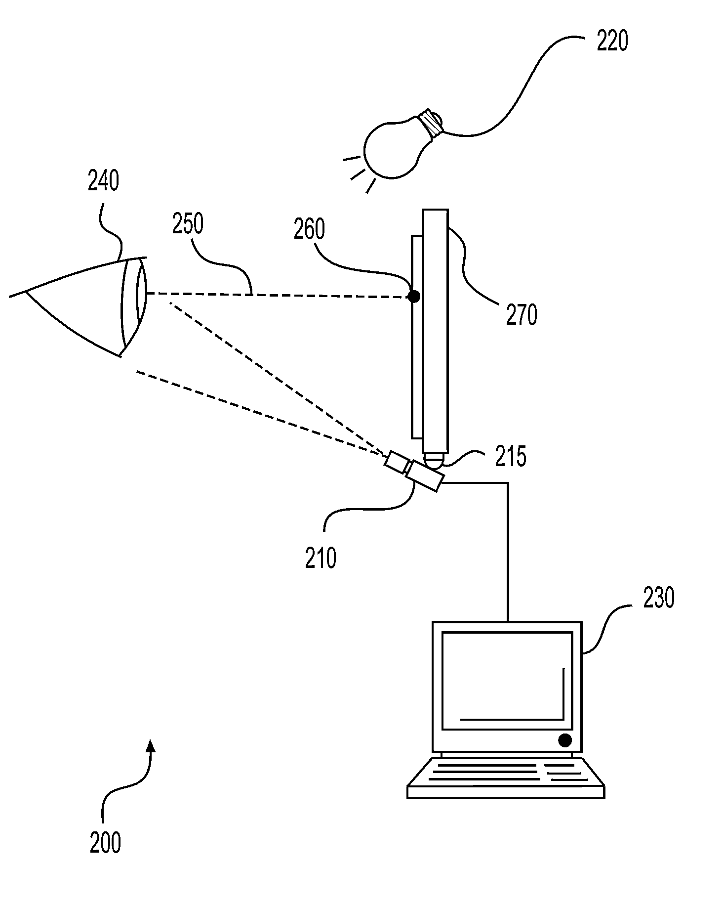
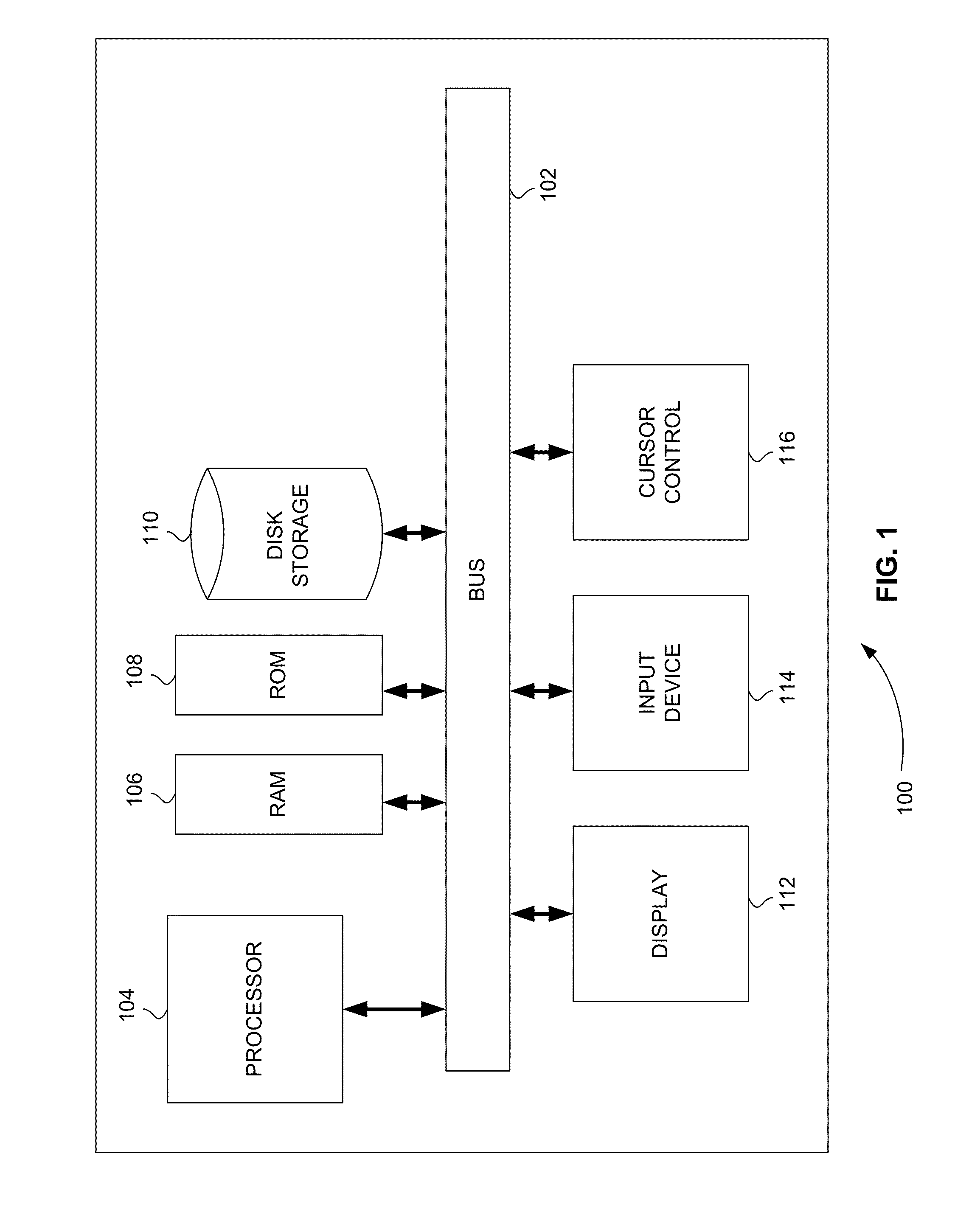
Computer-Implemented System

[0011]FIG. 1 is a block diagram that illustrates a computer system 100, upon which embodiments of the present teachings may be implemented. Computer system 100 includes a bus 102 or other communication mechanism for communicating information, and a processor 104 coupled with bus 102 for processing information. Computer system 100 also includes a memory 106, which can be a random access memory (RAM) or other dynamic storage device, coupled to bus 102 for storing instructions to be executed by processor 104. Memory 106 also may be used for storing temporary variables or other intermediate information during execution of instructions to be executed by processor 104. Computer system 100 further includes a read only memory (ROM) 108 or other static storage device coupled to bus 102 for storing static information and instructions for processor 104. A storage device 110, such as a magnetic disk or optical disk, is provided and coupled to bus 102 for storing infor...


PUM


Abstract

A system and method are disclosed for using a camera image of a user's eye as a visual stimulus for the calibration point in an eyetracking calibration system. A camera image of a user's eye is generated on a user display using an eyetracker. The camera image of the user's eye is used as a visual stimulus of a calibration point. In an embodiment, the center of the pupil of the camera image of the user's eye represents the coordinates of the calibration point on the user display. In another embodiment, the center of the corneal reflection of the camera image of the user's eye represents the coordinates of the calibration point on the user display.

Description

CROSS-REFERENCE TO RELATED APPLICATION[0001]This application claims the benefit of U.S. Provisional Patent Application No. 61 / 955,877, filed Mar. 20, 2014, the content of which is incorporated by reference herein in its entirety.INTRODUCTION[0002]In order to obtain accurate measurements of an eye's orientation and / or of its gazepoint in space, a calibration process is an important part of using many eyetracking systems. During the calibration process, a user is typically asked to look at a specific point or set of points in space, such as a dot or visual stimulus on a computer screen. For some users, such as children or people with certain disabilities, fixating on a calibration dot can be difficult, tedious or visually unattractive, or the user may just not be inclined to look at the calibration stimulus. As a result, new methods of attracting and maintaining a user's attention during the calibration process are needed.BRIEF DESCRIPTION OF THE DRAWINGS[0003]The skilled artisan will...

Claims


Application Information

Patent Timeline
Patent Type & Authority Applications(United States)
IPC IPC(8): G06T7/00G06K9/00
CPCG06T7/0018G06T2207/30041G06T2207/10016G06K9/00604G06T7/73G06V40/19
Inventor MAHER, WILLIAMCLEVELAND, DIXON
Owner EYEGAZE INC
Why Eureka
Try Eureka