
Multiple levels of logical routers

a logical router and multi-level technology, applied in the field of multi-level logical routers, can solve the problems of not being easily performed, requiring additional processing techniques for logical routers,

Active Publication Date: 2015-09-24
NICIRA
View PDF4 Cites 185 Cited by
  • Summary
  • Abstract
  • Description
  • Claims
  • Application Information

AI Technical Summary

Benefits of technology

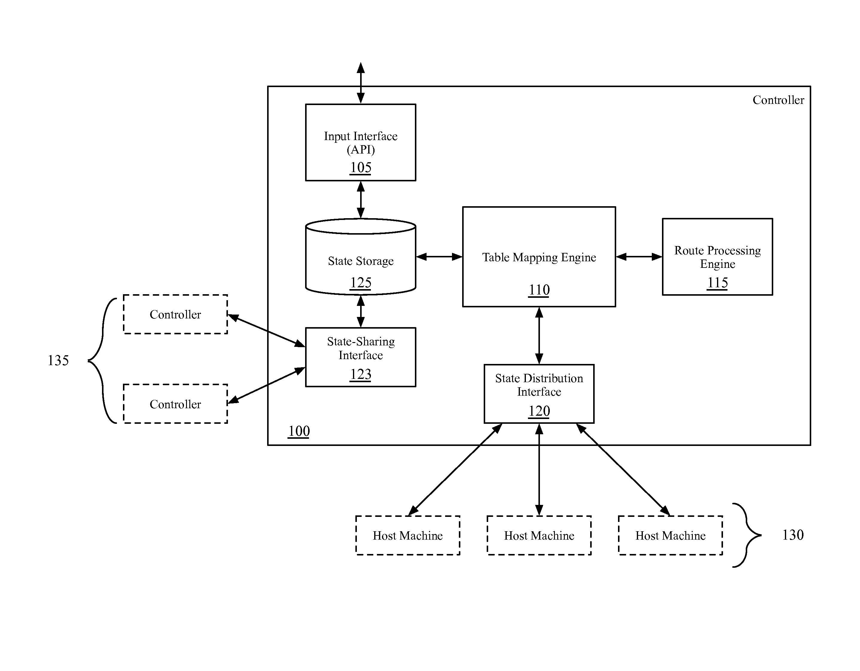
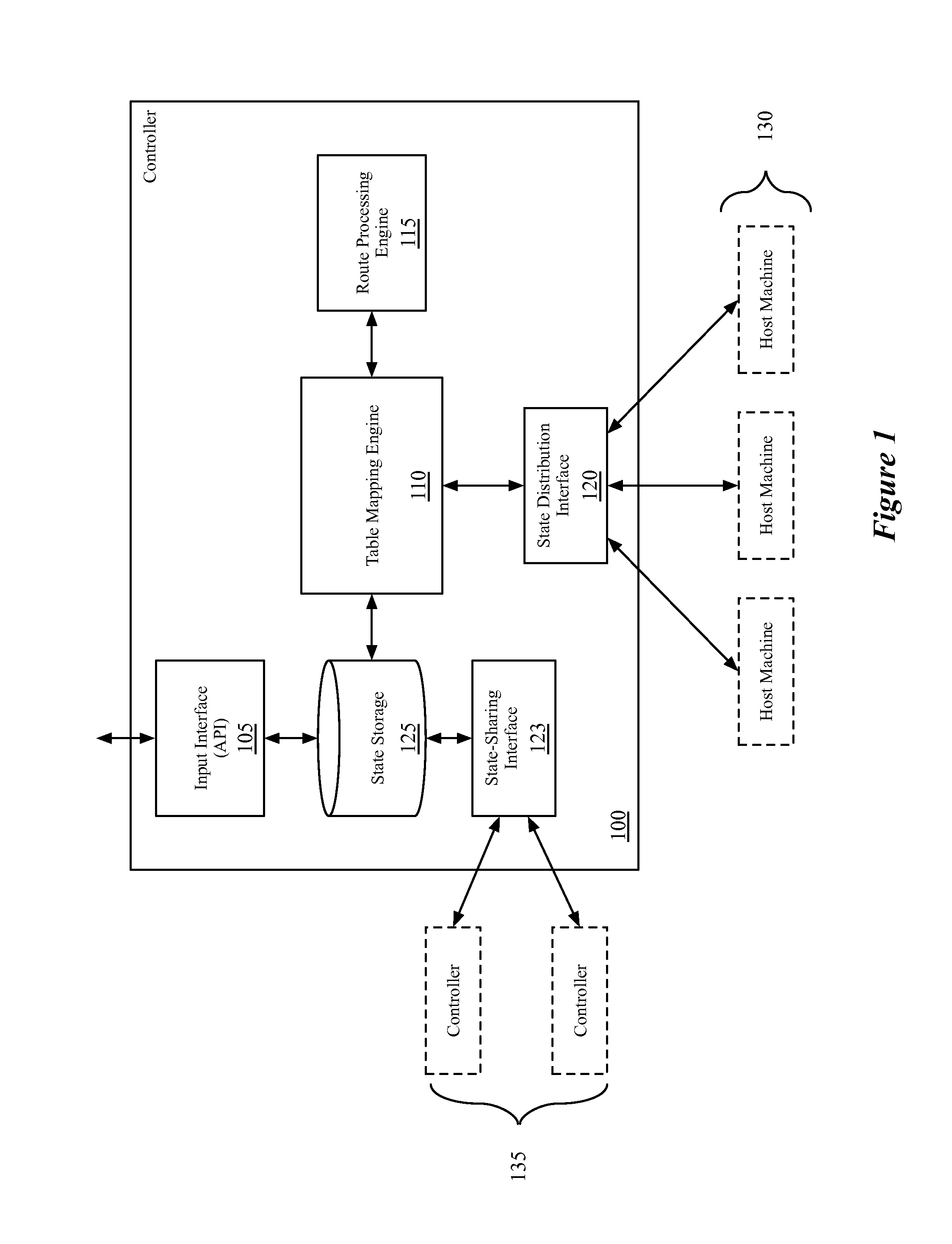
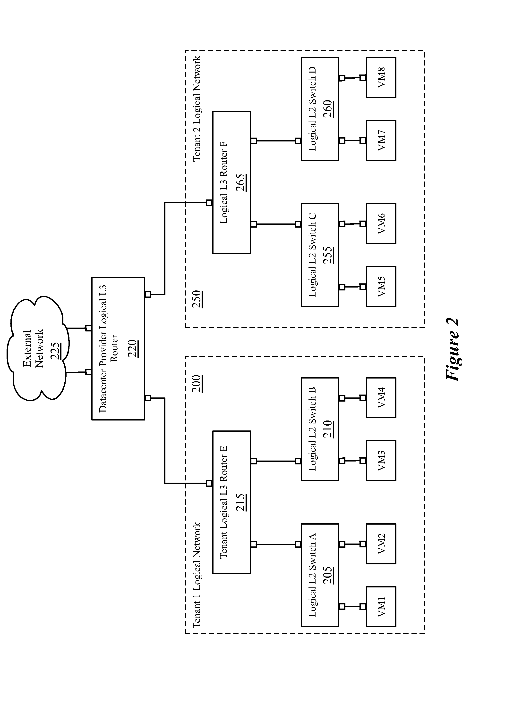
This patent describes a way to create logical routers within a virtualized network. These routers are managed by a datacenter provider to handle traffic in and out of the datacenter. The tenant logical routers provide logical routing for a single tenant, allowing them to connect with multiple logical switches. The tenant logical routers also connect to a provider logical router to receive and send traffic to external hosts. This setup allows the datacenter administrator to manage the traffic within the datacenter.

Problems solved by technology

Adding different types of routes to logical routers would pose the problem of requiring additional processing techniques for the logical routers, which may not be easily performed by the software forwarding elements often used to implement such logical routers.

Method used


Image

  • Multiple levels of logical routers
  • Multiple levels of logical routers
  • Multiple levels of logical routers

Examples


Embodiment Construction

[0030]In the following detailed description of the invention, numerous details, examples, and embodiments of the invention are set forth and described. However, it will be clear and apparent to one skilled in the art that the invention is not limited to the embodiments set forth and that the invention may be practiced without some of the specific details and examples discussed.

[0031]Some embodiments provide a network control system that enables the connection of logical routers to each other, and the propagation of routes between the logical routers. In some embodiments, the logical routers are managed by one or more network controllers, which receive input to define the logical routers and compute additional route information for the logical routers. The computation of additional route information may include the propagation of routes specified for one logical router to a different logical router. In order for a logical router to be implemented in a physical network managed by a ne...


PUM


Abstract

Some embodiments provide a managed network for implementing a logical network for a tenant. The managed network includes a first set of host machines and a second set of host machines. The first set of host machines is for hosting virtual machines (VMs) for the logical network. Each of the first set of host machines operates a managed forwarding element that implements a first logical router for the tenant logical network and a second logical router to which the first logical router connects. The implementation of the second logical router is for processing packets entering and exiting the tenant logical network. The second set of host machines is for hosting L3 gateways for the second logical router. The L3 gateways connect the tenant logical network to at least one external network.

Description

BACKGROUND[0001]In traditional physical networking, routes come in three types—connected, static, and dynamic. Connected routes are those determined automatically based on local interface information. When an interface has an address configured in a subnet, then the router has a directly connected route to that subnet. Static routes are those manually configured at the router, and dynamic routes are learned from other routers via routing protocols (e.g., BGP, OSPF, IGP, etc.). As this may result in a router being presented with multiple routes for the same IP address, routers perform various processing techniques in order to choose between these routes.[0002]Virtualized networks may also have routers, referred to as logical routers. Previous implementations of logical routers have only used connected routes, however, generated based on the IP prefix configured on the port of the logical router. Adding different types of routes to logical routers would pose the problem of requiring a...

Claims


Application Information

Patent Timeline
IPC IPC(8): H04L29/06H04L12/741H04L45/586H04L45/74
CPCH04L45/74H04L69/22H04L45/586H04L41/0894H04L41/0895H04L45/54H04L45/566G06F2009/45595H04L12/28H04L49/70H04L41/0803H04L41/0876H04L41/0879H04L41/0883H04L41/0886H04L41/0893H04L41/0889H04L41/08H04L12/46H04L67/1097
Inventor NEGINHAL, SRINIVASZHANG, RONGHUA
Owner NICIRA
Learn More