Method and apparatus to produce re-focusable vision by direct retinal projection with mirror array
a technology of direct retinal projection and mirror array, applied in the field of three-dimensional visual perception technology, can solve the problems of limiting the ability of prior art to re-produce, prior art 3d vision being obvious deviation from reality, and not allowing viewers to view all objects within the same scene clearly
- Summary
- Abstract
- Description
- Claims
- Application Information
AI Technical Summary
Benefits of technology
Problems solved by technology
Method used
Image
Examples
first embodiment
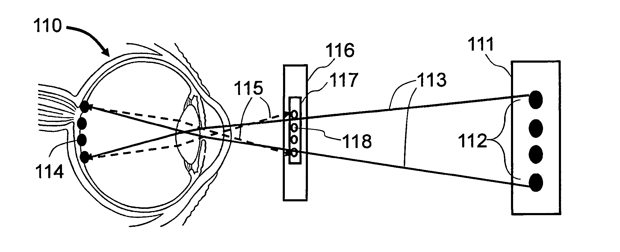
[0120]Now, coming back to the For the Step 103 of calculating the desired focus depth (Step 103) and retrieving image (Step 104), a computing system is used to obtain information of viewer's eye-lens, eyeball or brainwave pattern change from the sensors sensing such information from the viewer, and calculate the desired re-focus depth of the viewer about the image currently shown to the viewer. For brain-pattern recognition of viewer's re-focus intention, a brain-wave pattern database also provides information to the computing system to compare to the received brain pattern. Calculation of intended focus depth in Step 103 can be computed by the eye-lens, or together with eye-ball change, information obtained in Step 102, and optionally together with the image currently being displayed to the viewer. An image capturing device, for example a camera, can be in close proximity to the viewer's eyes to capture the scene that the viewer is currently being exposed to, wherein the eye-lens ...
second embodiment
[0132]FIG. 20 is a schematic flow diagram illustrating the second embodiment wherein eye-lens and eye-ball sensing of eye-information are used. All other steps, descriptions and procedures are same as in FIG. 18 case, except Step-1001 and Step-1002 are removed, wherein 205 recording media or recorded image database already exists and contains images simultaneously recorded from the same scene with different focus depth.
[0133]FIG. 21 is a schematic flow diagram illustrating the second embodiment wherein brain-wave pattern sensing of re-focus intention are used. All other steps, descriptions and procedures are same as in FIG. 19 case, except Step-1001 and Step-1002 are removed, wherein 215 recording media or recorded image database already exists and contains images simultaneously recorded from the same scene with different focus depth.
[0134]The third embodiment of the current invention is for enhanced human vision. The method according to the third embodiment includes the steps of: (...
third embodiment
[0138]FIG. 22 is a schematic flow diagram illustrating the third embodiment wherein eye-lens and eye-ball sensing of eye-information are used, including: (Step-3001) A scene 221 of objects is recorded by a recording device 223 having a focus depth adjustment component 224 as in 222; (Step-3002) A sensor 229 is positioned in proximity to the viewer's eye 220 and collects the re-focusing information or data from viewer's eye 220; (Step-3003) The said re-focusing data is transmitted as in 2293 to the device 228 for computing desired focus depth of the viewer; (Step-3004) The device 228 computes the desired focus depth of the viewer and determines the adjustment needed in said focus depth adjustment component 224; (Step-3005) The device 228 sends request to focus depth adjustment component 224 to adjust to desired focus depth of the viewer as in 2294; (Step-3006) The recording device 223 records image of current scene 221 of objects with adjusted focus depth adjustment component 224 and...
PUM
 Abstract
Description
Claims
Application Information
 - R&D
- Intellectual Property
- Life Sciences
- Materials
- Tech Scout
- Unparalleled Data Quality
- Higher Quality Content
- 60% Fewer Hallucinations
Browse by: Latest US Patents, China's latest patents, Technical Efficacy Thesaurus, Application Domain, Technology Topic, Popular Technical Reports.
© 2025 PatSnap. All rights reserved.Legal|Privacy policy|Modern Slavery Act Transparency Statement|Sitemap|About US| Contact US: help@patsnap.com


