Dental device comprising surgical template and false teeth set and related methods

a dental device and template technology, applied in the field of dental surgery, can solve the problems of imperfect bores, temporary or permanent paresthesia, difficult and accurate placement of implants within the jawbone, etc., and achieve the effect of shortening the surgery time for implantation and greater precision in placemen

Inactive Publication Date: 2015-10-01
INSTITUT STRAUMANN AG
View PDF5 Cites 28 Cited by
  • Summary
  • Abstract
  • Description
  • Claims
  • Application Information

AI Technical Summary

Benefits of technology

[0041]The device of the invention when implanted and converted to a denture prosthesis provides for the appearance of natural teeth while being fixed in the jaw, providing aesthetic benefits for an edentulous or partially edentulous patient. Further, the invention may provide for shorter surgery times for implantation of the device as well as greater precision in placement compared to conventional devices. In addition, the device may be converted to a temporary or final prosthesis. The device can be used with a variety of implants for implantation into jaw bone.

Problems solved by technology

Accurate placement of the implants within the jawbone is a difficult task.
However, this method can readily result in imperfect bores due to space limitations associated with working inside a patient's mouth.
If the drilling axis is not properly chosen, the installed implants might cause damage to the tissues and muscle surrounding the area of implantation and subsequently cause temporary or permanent paresthesia.
Furthermore, other problems can result from flawed or imperfect implant holes, such as uneven force distribution, insufficient bone growth around the implant, secondary infections, and ultimately, implant failure.
Each surgical stent commonly used is custom-built and these devices are only useful for a single patient, are costly to fabricate, and they require a number of intermediary office and laboratory steps to take an impression of the patient's arch and create a cast model from which the surgical stent is formed.
The procedure for manufacturing dental implant superstructures as is conventionally known in the art is time-consuming and sometimes results in imperfect structures or defects in the visual appearance of the dentures to be placed over the superstructure.

Method used


Image

  • Dental device comprising surgical template and false teeth set and related methods
  • Dental device comprising surgical template and false teeth set and related methods
  • Dental device comprising surgical template and false teeth set and related methods

Examples


Embodiment Construction

[0088]Reference will now be made in detail to various exemplary embodiments of the invention. It is to be understood that the following discussion of exemplary embodiments is not intended as a limitation on the invention. Rather, the following discussion is provided to give the reader a more detailed understanding of certain aspects and features of the invention.

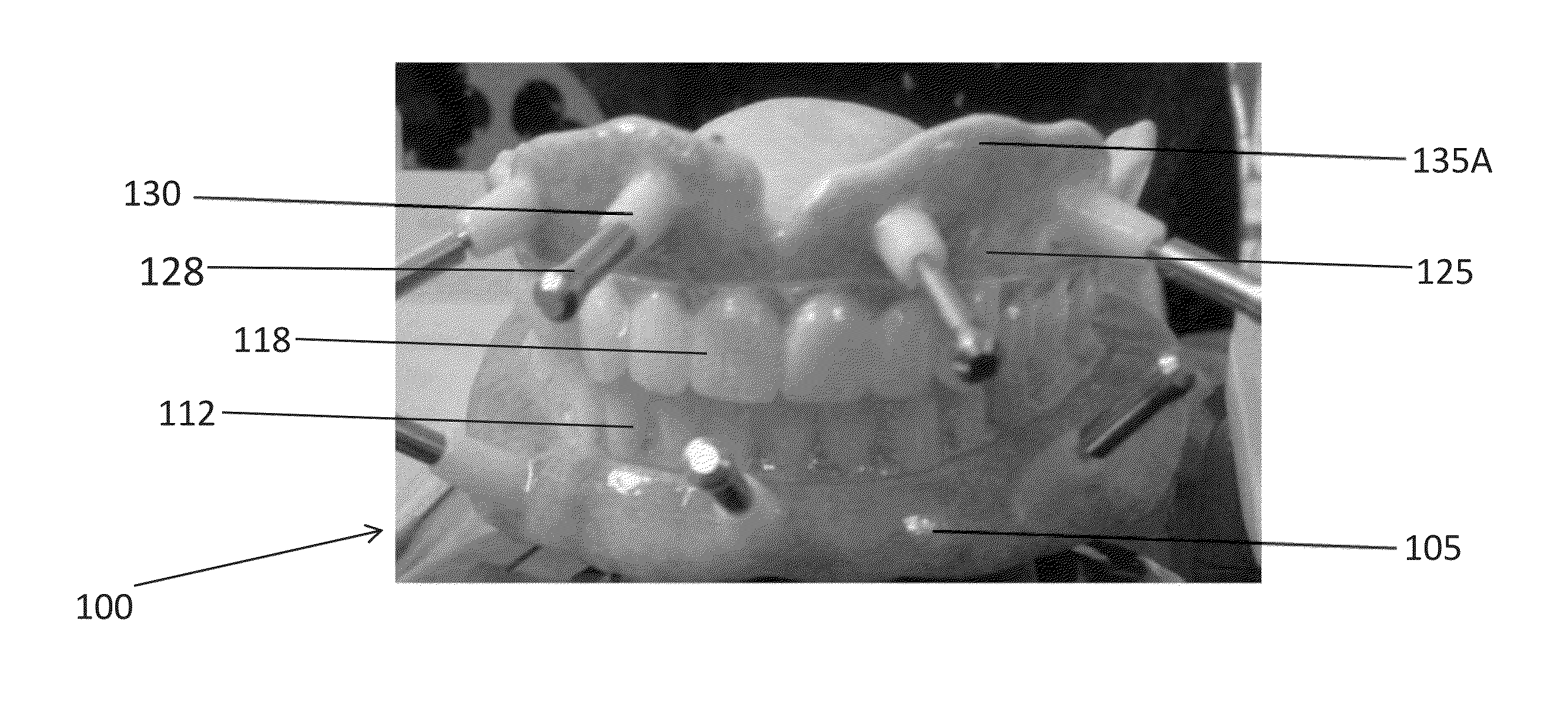
[0089]In one embodiment, the present invention is a two-part denture prosthesis or device comprising a surgical template or guide and removable false teeth set for both the mandibular and maxillary jaw. The surgical template and false teeth set may be configured to fit together in an interlocking configuration. The surgical guide may exist as two components that are each configured to fit the top (maxilla) or bottom (mandible) portion of a patient's jaw when placed inside the mouth. The surgical guide may have one or more holes that may serve as drilling sites. The holes may be positioned so that osteotomies may be drilled d...


PUM


Abstract

A dental device is described. The dental device includes a surgical template having one or more sites for drilling osteotomies in the maxillary or mandibular jaw and a false teeth set. The surgical template and false teeth set are configured to fit together to form a denture prosthesis that can be implanted in a patient. Also described are a method for creating a surgical dental template, a method for implanting a dental prosthesis, and a method for reducing jaw bone in a patient.

Description

CROSS-REFERENCE TO RELATED APPLICATIONS[0001]The present application relies on the disclosure of and claims priority to and the benefit of the filing dates of U.S. Provisional Application No. 61 / 971,804 and U.S. Provisional Application No. 61 / 971,810, both filed on Mar. 28, 2014, and U.S. Provisional Application No. 62 / 052,988, filed Sep. 19, 2014, the disclosures of which are hereby incorporated by reference herein in their entireties.BACKGROUND OF THE INVENTION[0002]1. Field of the Invention[0003]The present invention relates to the field of dental surgery. More particularly, the present invention relates to a combination surgical template and false teeth set that fit together to form an implantable denture. The present invention also relates to methods for manufacturing a surgical dental template, methods for installing a denture prosthesis in a partially edentulous patient, and method for reducing jaw bone in a patient.[0004]2. Description of Related Art[0005]The use of dental p...

Claims


Application Information

Patent Timeline
Patent Type & Authority Applications(United States)
IPC IPC(8): A61C1/08A61C13/01A61C13/08A61C8/00
CPCA61C1/084A61C8/0089A61C13/08A61C13/01A61C8/0009A61C13/0004A61C9/0046A61C2201/005A61B6/032A61B6/14A61C13/09
Inventor WATSON, JASONTSAI, RON
Owner INSTITUT STRAUMANN AG
Why Eureka
Try Eureka