Lift Arm and Coupler Control System

a control system and coupler technology, applied in mechanical machines/dredgers, analogue processes for specific applications, instruments, etc., can solve problems such as limited adaptability to changes

Inactive Publication Date: 2015-10-01
CATERPILLAR INC
View PDF6 Cites 32 Cited by
  • Summary
  • Abstract
  • Description
  • Claims
  • Application Information

AI Technical Summary

Benefits of technology

[0009]In yet another aspect of the present disclosure, a loader is provided. The loader may include a frame, a lift arm assembly movably coupled to the frame, a coupler pivotally coupled to the lift arm assembly, an operator interface configured to generate a baseline command for operating one or more of the lift arm assembly and the coupler in response to operator input, a lift arm position sensor coupled to the lift arm assembly and configured to measure a lift arm position, an inclinometer coupled to the coupler

Problems solved by technology

However, control algorithms typically used in these configurations often rely on relatively fragmented sensor data to

Method used


Image

  • Lift Arm and Coupler Control System
  • Lift Arm and Coupler Control System
  • Lift Arm and Coupler Control System

Examples


Embodiment Construction

[0017]Reference will now be made in detail to specific embodiments or features, examples of which are illustrated in the accompanying drawings. Generally, corresponding reference numbers will be used throughout the drawings to refer to the same or corresponding parts.

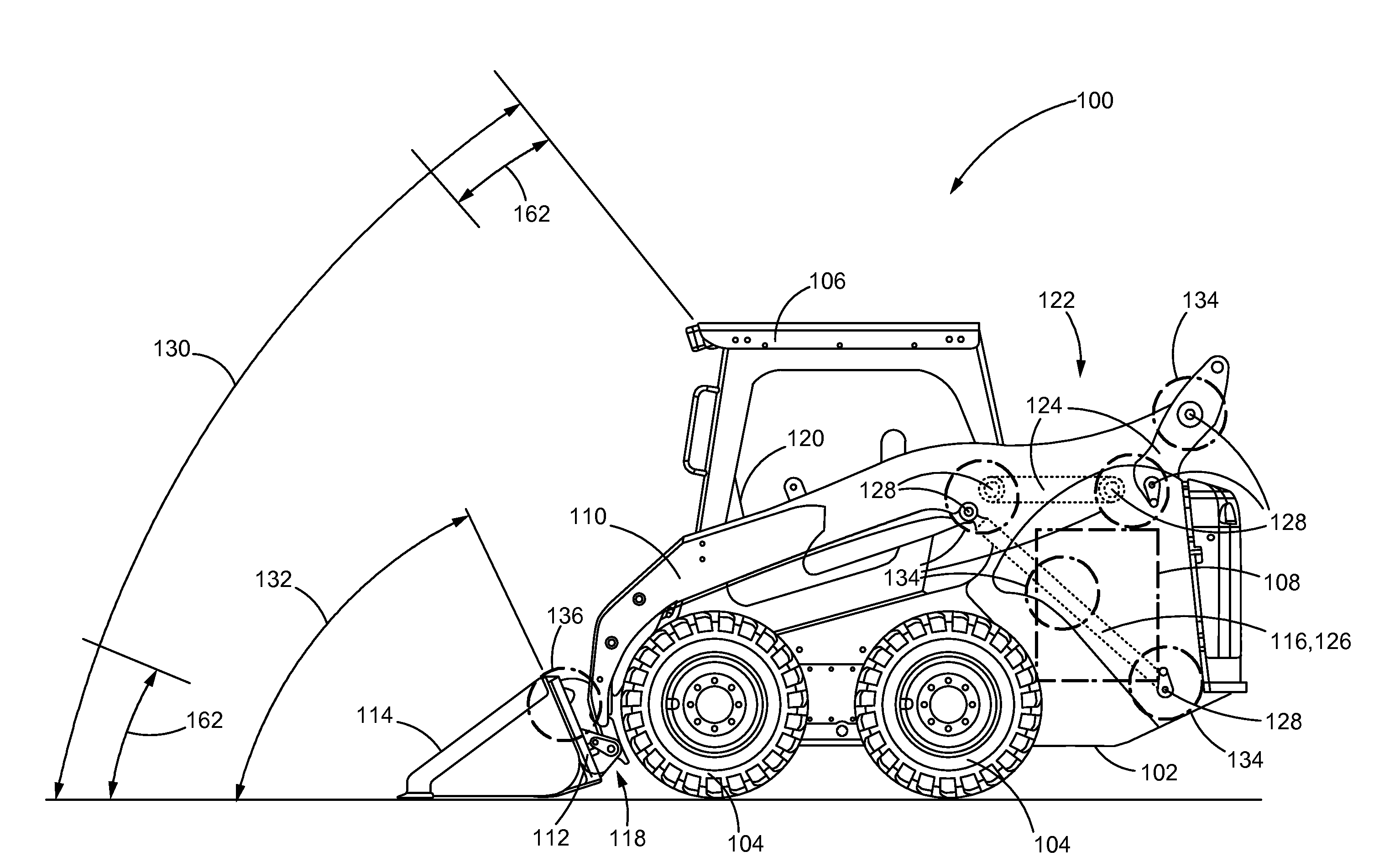
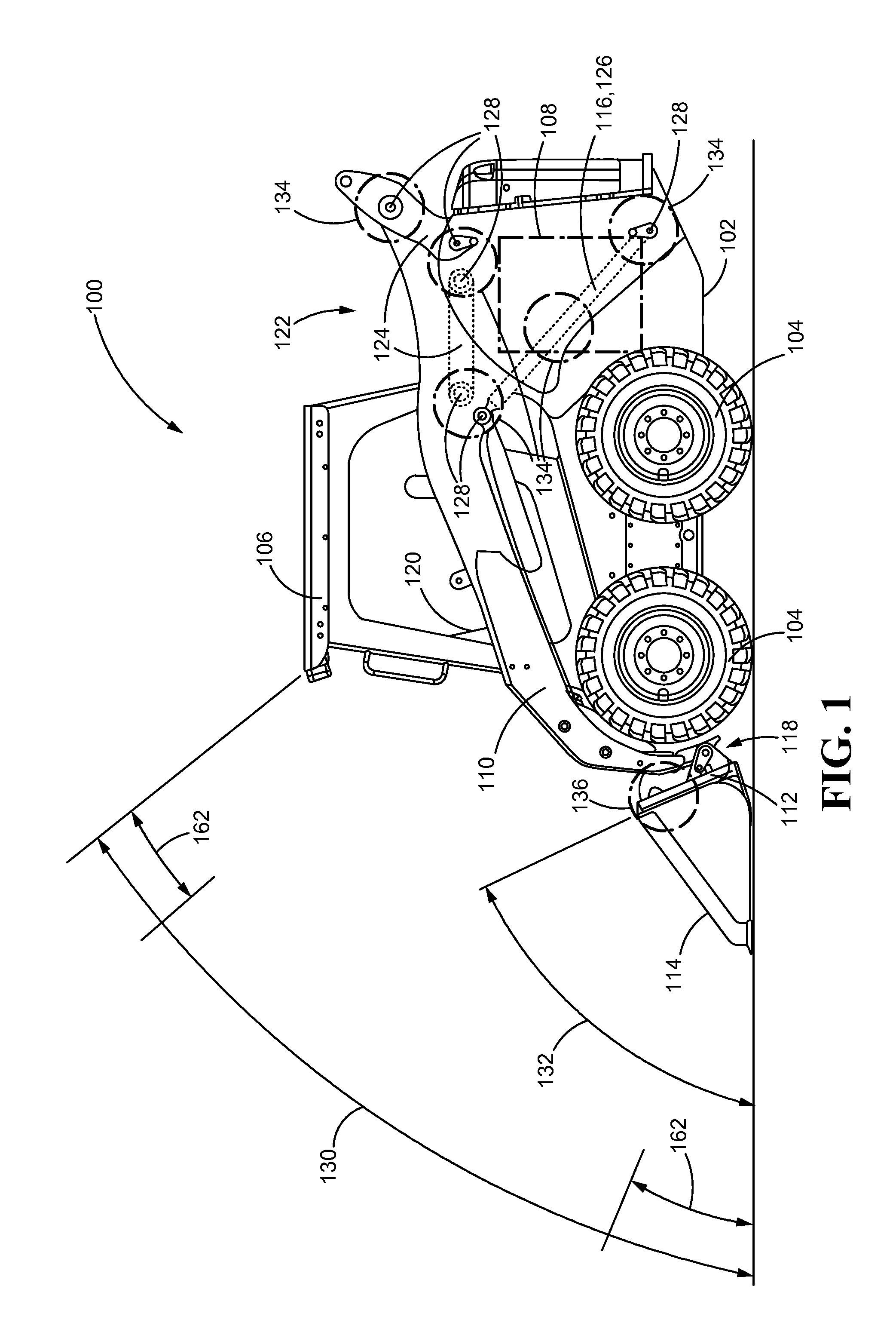
[0018]Referring now to FIG. 1, one exemplary machine or loader 100 is provided. As shown, the loader 100 may generally include a frame 102 which supports traction devices 104, a cab 106, and a power source 108, such as a hydrostatic drive or an engine, and the like. The loader 100 may further include one or more lift arms 110 that are movably coupled to the frame 102 and a coupler 112 that is pivotally coupled or mounted to the working end of the lift arms 110 to which a suitable implement 114, such as a bucket, or the like, may be attached. In particular, the coupler 112 may employ pins, latches, hooks, fasteners, or any other suitable mechanism for interchangeably or non-interchangeably coupling an implement 114 to th...


PUM


Abstract

A control system for a loader having a frame, a lift arm assembly, a coupler, and an operator interface is provided. The control system may include a lift arm position sensor coupled to the lift arm assembly and configured to measure a lift arm position, an inclinometer disposed on the coupler configured to measure a coupler angle, and a controller in electrical communication with each of the lift arm position sensor, the inclinometer and the operator interface. The controller may be configured to receive a baseline command from the operator interface for operating one or more of the lift arm assembly and the coupler, monitor the lift arm position and the coupler angle, and generate at least one command for operating one or more of the lift arm assembly and the coupler based on one or more of the baseline command, the lift arm position and the coupler angle.

Description

TECHNICAL FIELD[0001]The present disclosure relates generally to lift arm assemblies, and more particularly, to systems and machines for controlling lift arm assemblies.BACKGROUND[0002]Certain machines may be fitted with different implements to be used in industries related to materials handling, construction, and the like. These machines typically include one or more lift arms for moving an implement attached thereto from a starting position to a desired ending position in order to perform a desired task. Such a machine is often used to transport materials, such as by lifting a given load of material from a first site, carrying the load to a second site, and dumping the material at the second site. The machine may often repeat the process by returning to the first site, lowering the implement to the starting position, lifting another load of the material, and so forth.[0003]Different features have been incorporated into such machines to facilitate operator control and reduce wear. ...

Claims


Application Information

Patent Timeline
IPC IPC(8): E02F3/43E02F3/34
CPCE02F3/3414E02F3/431E02F3/433E02F3/434E02F9/265
Inventor FREDRICKSON, ANDREWMAHONEY, JASONLYNCH, CAMERON EDWARDPINTHER, II, GEORGE CART
Owner CATERPILLAR INC
Why Eureka
Try Eureka