Hydraulic shock absorber

a technology of shock absorber and shock absorber, which is applied in the direction of shock absorber, vibration damper, spring/damper, etc., can solve the problems of complex time for energizing the stepping motor, difficulty in defining the desynchronization section, and difficulty in controlling the amount of electricity supplied to the stepping motor, so as to prevent the desynchronization of the electric motor and the feed screw mechanism from occurring, the damping force can be adjusted stably, and the effect o

Active Publication Date: 2015-10-01
HITACHI ASTEMO LTD
View PDF12 Cites 11 Cited by
  • Summary
  • Abstract
  • Description
  • Claims
  • Application Information

AI Technical Summary

Benefits of technology

[0019]With the configuration of [1], when the reaction force acting on the push rod exceeds the thrust of the electric motor, the second slider slides with respect to the first slider against the biasing force of the set spring, and, because no reaction force equal to or greater than the thrust of the electric motor acts on the electric motor, desynchronization of the electric motor is prevented from occurring. As a result, the damping force can be adjusted stably, and damage to the electric motor and the feed screw mechanism is prevented.
[0020]With the configuration of [2], even when the second slider moves due to excessive reaction force acting on the push rod, the second slider is brought into abutment with the stopper and consequently prevented from sliding any farther. Consequently, the stopper receives some of the excessive reaction force so that the excessive reaction force does not act directly on the electric motor, reliably preventing the occurrence of desynchro

Problems solved by technology

Unfortunately, there is a problem with the hydraulic shock absorber proposed in Patent Literature 2 that defining the desynchronization section is difficult because

Method used


Image

  • Hydraulic shock absorber
  • Hydraulic shock absorber
  • Hydraulic shock absorber

Examples


Embodiment Construction

[0030]An embodiment of the present invention is described hereinafter with reference to accompanying drawings.

[Configuration of Hydraulic Shock Absorber]

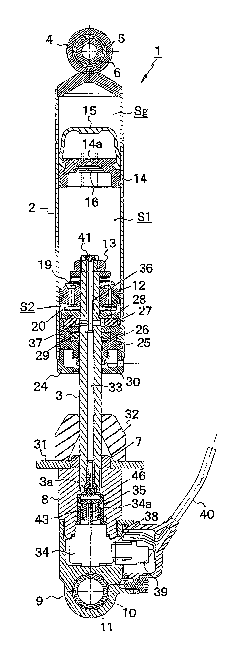
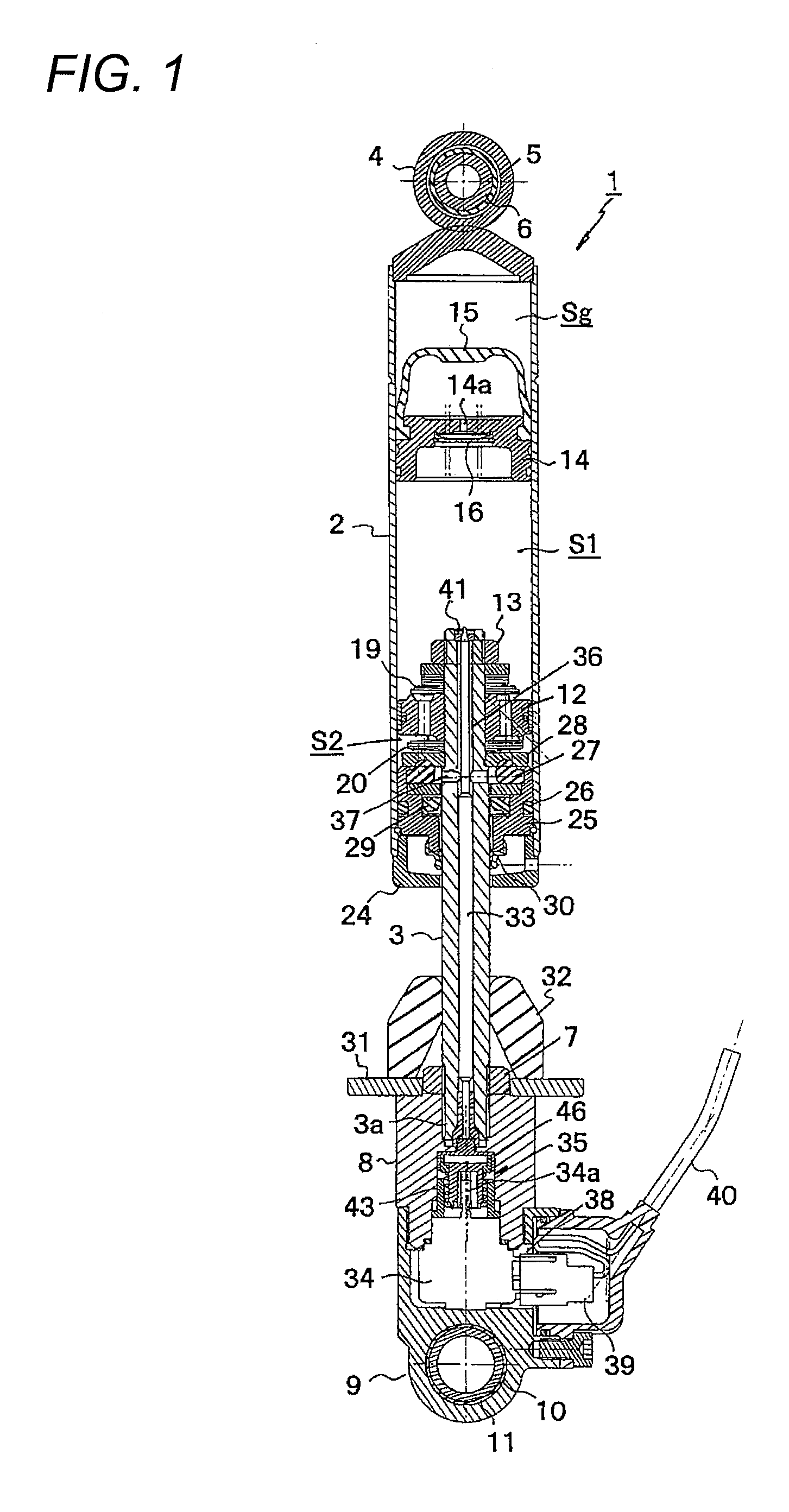
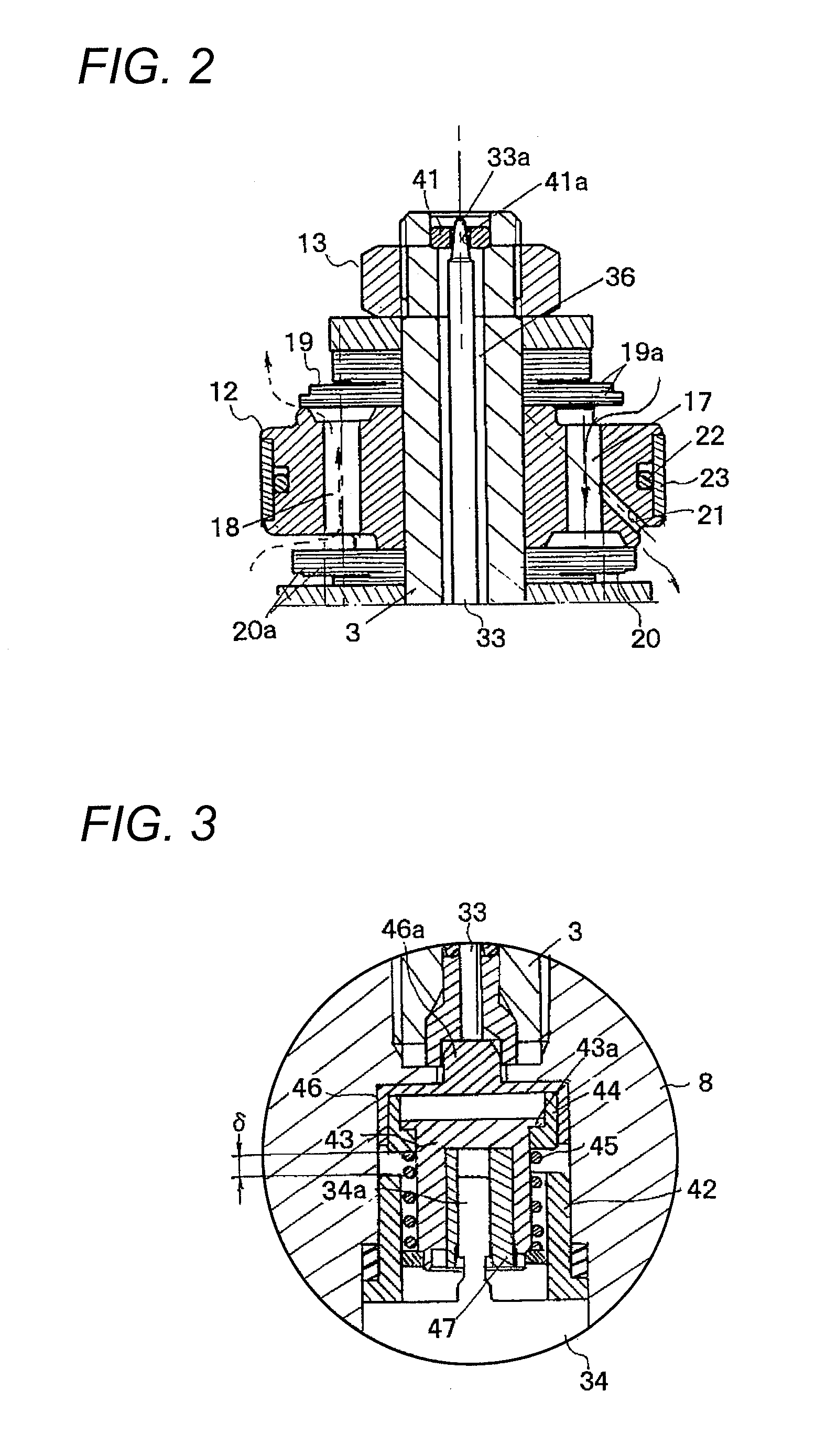
[0031]FIG. 1 is a vertical cross-sectional view of a hydraulic shock absorber according to the present invention. FIG. 2 is an enlarged detail view of a piston portion shown in FIG. 1. FIG. 3 is an enlarged detail view of a feed screw mechanism portion shown in FIG. 1. FIG. 4 is a view same as FIG. 3, showing a state in which a second slider of a damping force adjustment unit slides. FIG. 5 is a view same as FIG. 3, showing a state in which the second slider of the damping force adjustment unit comes into abutment with a stopper via a spring guide.

[0032]The hydraulic shock absorber 1 according to the present embodiment is an inverted rear cushion that suspends a rear wheel of a motorcycle, not shown, with respect to a vehicle body, and is configured by inserting, from below, part of a hollow piston rod 3 on an axle side into a cylin...


PUM


Abstract

A hydraulic shock absorber includes a damping force generation unit and a damping force adjustment unit. The damping force adjustment unit includes a push rod that changes an opening area of an oil path formed in a piston rod, an electric motor functioning as a driving source, and a feed screw mechanism that converts rotation of the electric motor into linear movement of the push rod. The feed screw mechanism includes a first slider that is screwed to an output shaft of the electric motor in an advanceable/retractable manner, a second slider is fitted movably to the first slider, and a set spring that pushes the second slider against one end of the push rod.

Description

CROSS-REFERENCE TO RELATED APPLICATIONS[0001]This application is based on and claims priority under 35 USC 119 from Japanese Patent Application No. 2014-062773 filed on Mar. 25, 2014, the entire content of which is incorporated herein by reference.BACKGROUND OF THE INVENTION[0002]1. Technical Field[0003]The present invention relates to a hydraulic shock absorber with a damping force adjustment unit.[0004]2. Related Art[0005]For instance, there are hydraulic shock absorbers provided in a motorcycle to suspend a rear wheel of the motorcycle in relation to a vehicle body which have a configuration in which a cylinder is mounted on one of a vehicle body side and an axle side, a piston rod is mounted on the other side, the piston rod is partially inserted in the cylinder, a piston fixed to an end portion of the piston rod that faces an inside of the cylinder is brought into sliding contact with an inner circumference of the cylinder in a slidable manner, and a suspension spring is interp...

Claims


Application Information

Patent Timeline
IPC IPC(8): F16F9/44F16F9/34
CPCF16F9/3405F16F9/44F16F9/461
Inventor OHTA, MASATOSHI
Owner HITACHI ASTEMO LTD
Why Eureka
Try Eureka