Optical Coordinate Measuring Device

a technology of optical coordinates and measuring devices, which is applied in the direction of measurement devices, mechanical measuring arrangements, instruments, etc., can solve the problems of deteriorating accuracy in measuring coordinates and the inability to accurately specify the position of the contact probe, so as to prevent damage reduce the impact transmitted to the holding part, and prevent the effect of deterioration in measurement accuracy due to a dimensional change in the prob

Active Publication Date: 2015-10-01
KEYENCE
View PDF2 Cites 4 Cited by
  • Summary
  • Abstract
  • Description
  • Claims
  • Application Information

AI Technical Summary

Benefits of technology

[0029]In this case, stress is not directly applied to the holding part from the outside. Further, even when an impact is applied to the housing due to falling, collision, or the like of the probe, the impact transmitted to the holding part is reduced by the buffer member. This prevents damage to the holding part.
[0030]According to the present invention, deterioration in measurement accuracy due to a dimensional change in the probe is prevented.

Problems solved by technology

In this case, it becomes impossible to accurately specify the position of the contact probe.
As a result, the accuracy in measurement of the coordinates deteriorates.

Method used


Image

  • Optical Coordinate Measuring Device
  • Optical Coordinate Measuring Device
  • Optical Coordinate Measuring Device

Examples


Embodiment Construction

(1) Configuration of Optical Coordinate Measuring Device

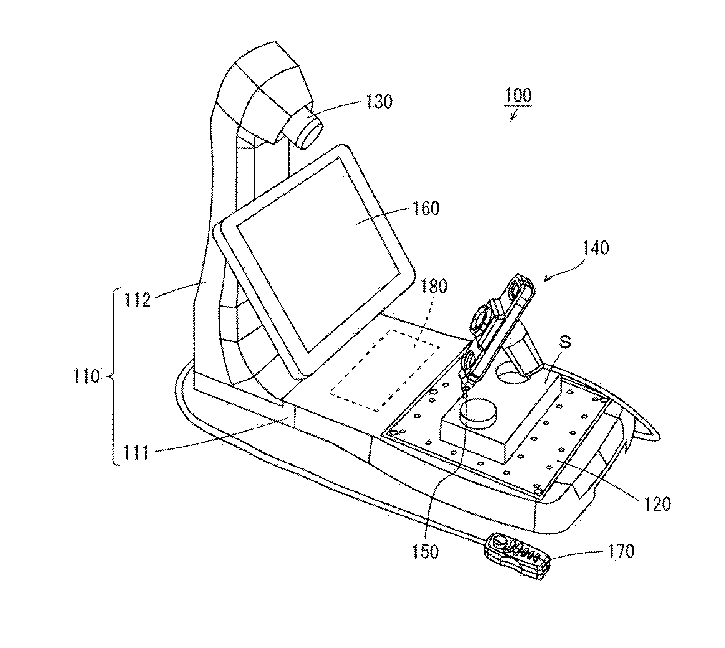
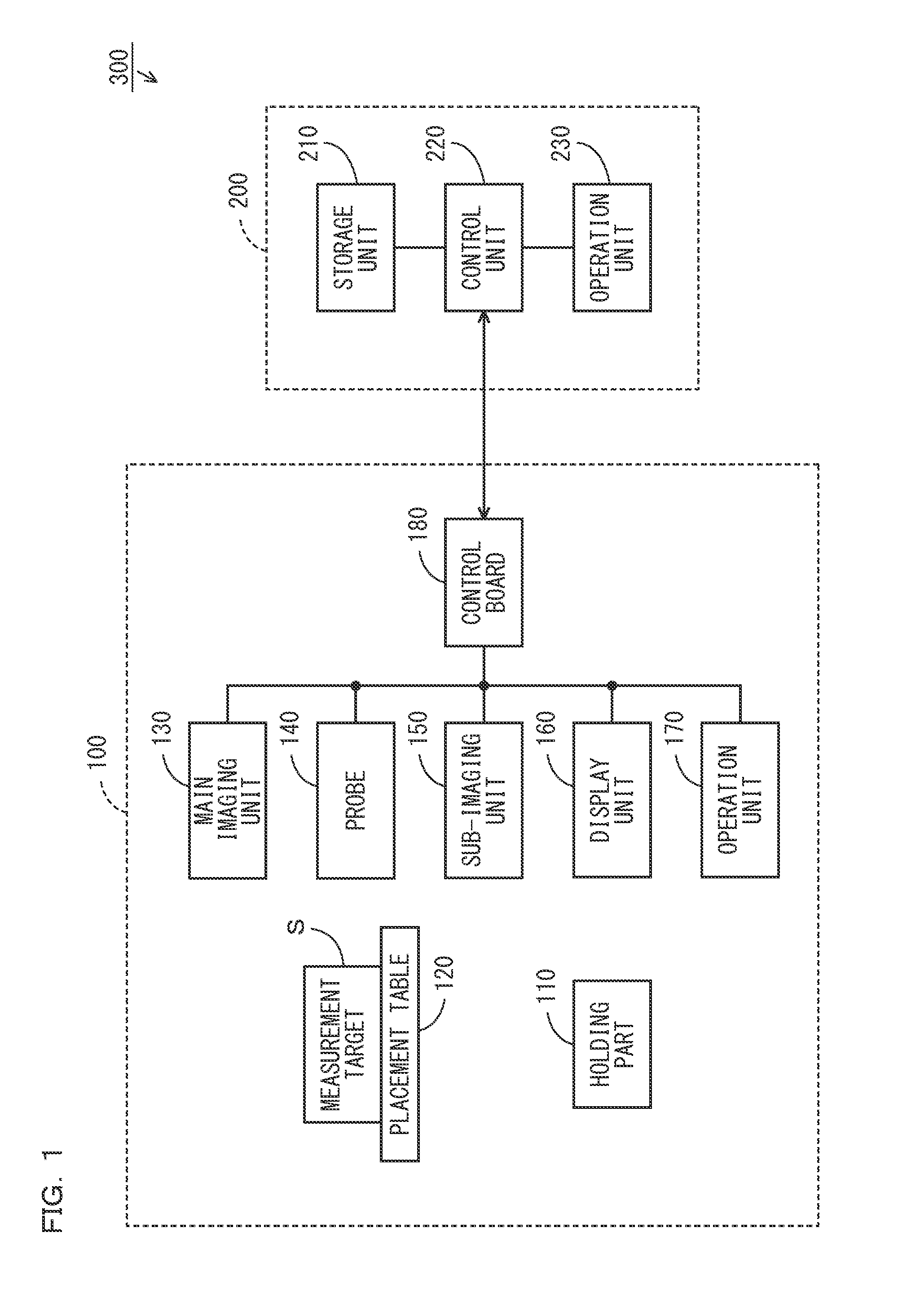
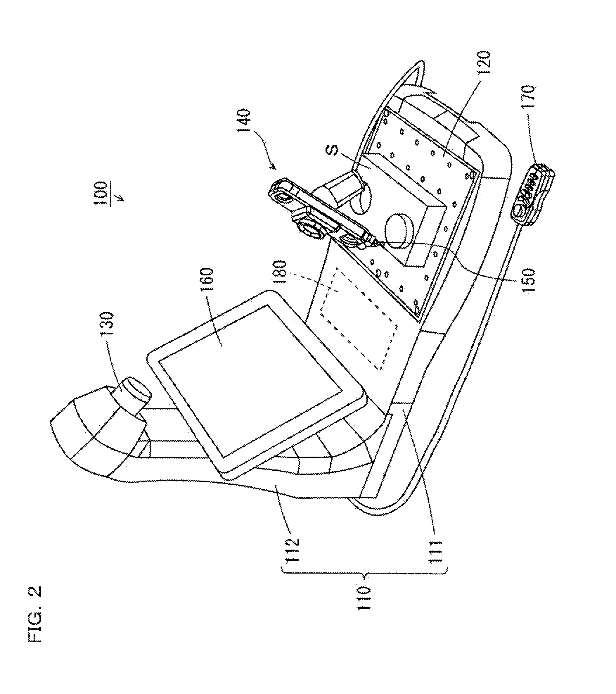
[0051]FIG. 1 is a block diagram showing a configuration of an optical coordinate measuring device according to one embodiment of the present invention. FIG. 2 is a perspective view showing a configuration of a measurement head of an optical coordinate measuring device 300 of FIG. 1. FIG. 3 is a perspective view showing a configuration of a probe of a measurement head 100 of FIG. 2. Hereinafter, the optical coordinate measuring device 300 according to the present embodiment will be described with reference to FIGS. 1 to 3. As shown in FIG. 1, the optical coordinate measuring device 300 is provided with the measurement head 100 and a processing device 200. The measurement head 100 includes a holding part 110, a placement table 120, a main imaging unit 130, a probe 140, a sub-imaging unit 150, a display unit 160, an operation unit 170, and a control board 180.

[0052]As shown in FIG. 2, the holding part 110 of the measurement head 1...


PUM


Abstract

Provided is an optical coordinate measuring device that prevents deterioration in measurement accuracy. A holding member is made of a material having low moisture absorption properties and a small linear expansion coefficient. A marker member is held by the holding member. The marker member includes a plate member made of glass. A light shielding mask is formed by printing on one surface of the plate member except for a plurality of circular regions. A light emitting substrate is arranged below the marker member. A plurality of light emitting elements are mounted on the upper surfaces of the light emitting substrates.

Description

CROSS-REFERENCE TO RELATED APPLICATIONS[0001]The present application claims foreign priority based on Japanese Patent Application No. 2014-069858, filed Mar. 28, 2014, the contents of which is incorporated herein by reference.BACKGROUND OF THE INVENTION[0002]1. Field of the Invention[0003]The present invention relates to an optical coordinate measuring device using a probe.[0004]2. Description of Related Art[0005]An optical coordinate measuring device is provided with a probe for designating a measurement position. An arbitrary position of a measurement target is designated as a measurement position by the probe, and coordinates of the measurement position are calculated. By calculating coordinates of a plurality of measurement positions on the measurement target, a size of a desired portion of the measurement target is measured.[0006]JP 06-511555 A describes a system for point by point measurement of spatial coordinates, which includes a data processor, a contact probe, and an angl...

Claims


Application Information

Patent Timeline
Patent Type & Authority Applications(United States)
IPC IPC(8): G01B11/00
CPCG01B11/005G01B5/008
Inventor IKEBUCHI, MASAYASU
Owner KEYENCE
Why Eureka
Try Eureka