Dynamic Pressure Sensor

a technology of dynamic pressure sensor and sensor body, which is applied in the direction of loudspeakers, mouthpiece/microphone attachments, instruments, etc., can solve the problem of membrane deflecting

Active Publication Date: 2015-10-01
INFINEON TECH AG
View PDF5 Cites 32 Cited by
  • Summary
  • Abstract
  • Description
  • Claims
  • Application Information

AI Technical Summary

Problems solved by technology

A pressure difference between the sealed volume and an external volume, such as the ambient environment in some cases, causes the membrane to deflect.

Method used


Image

  • Dynamic Pressure Sensor
  • Dynamic Pressure Sensor
  • Dynamic Pressure Sensor

Examples


Embodiment Construction

[0022]The making and using of various embodiments are discussed in detail below. It should be appreciated, however, that the various embodiments described herein are applicable in a wide variety of specific contexts. The specific embodiments discussed are merely illustrative of specific ways to make and use various embodiments, and should not be construed in a limited scope.

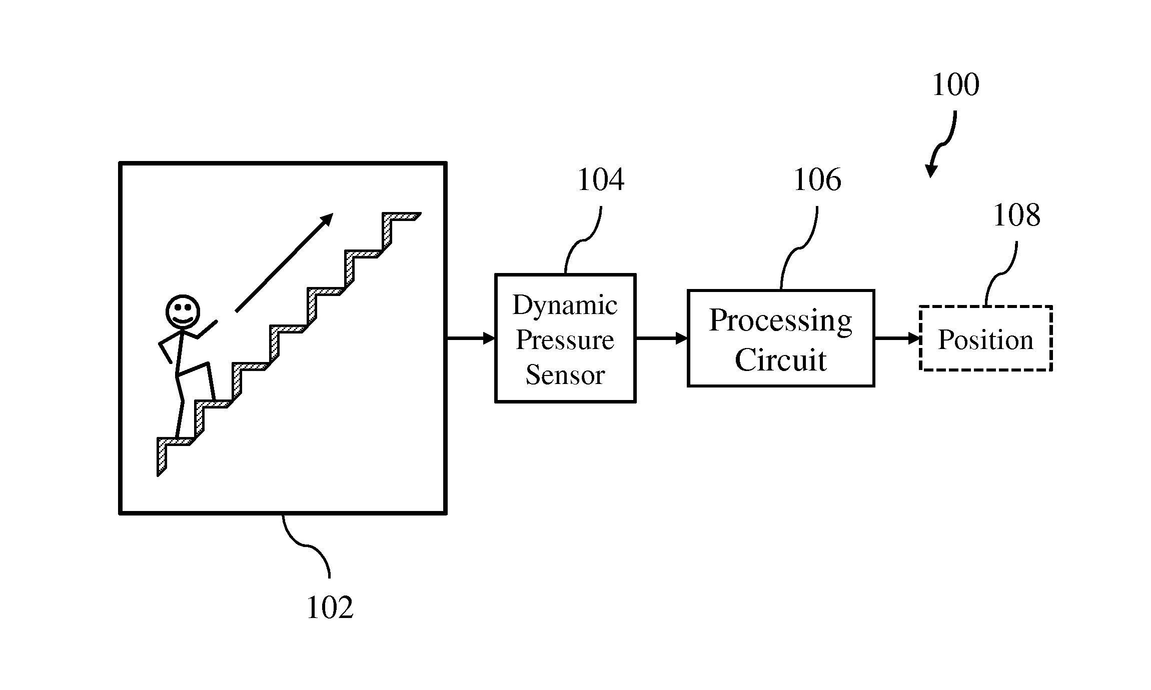
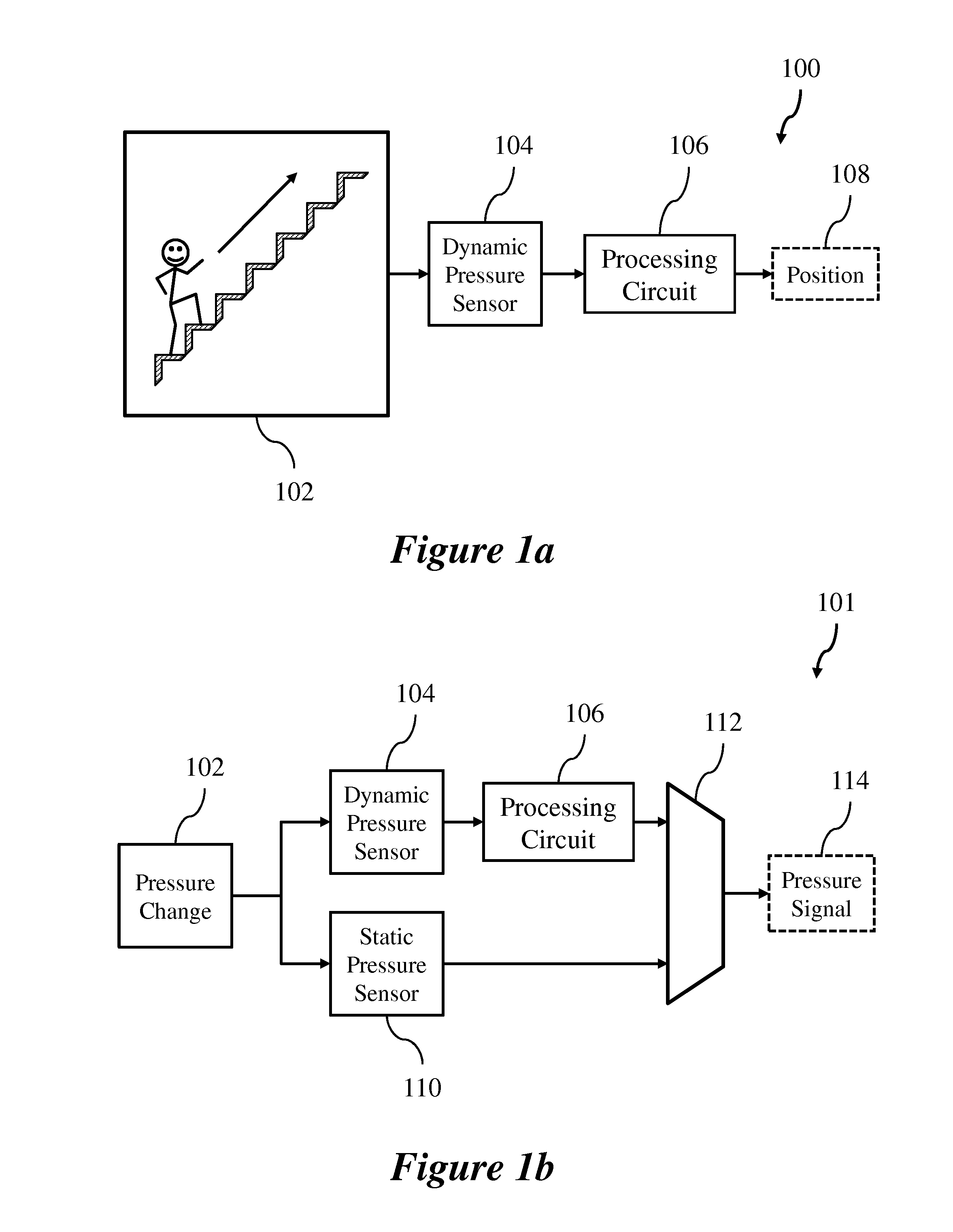
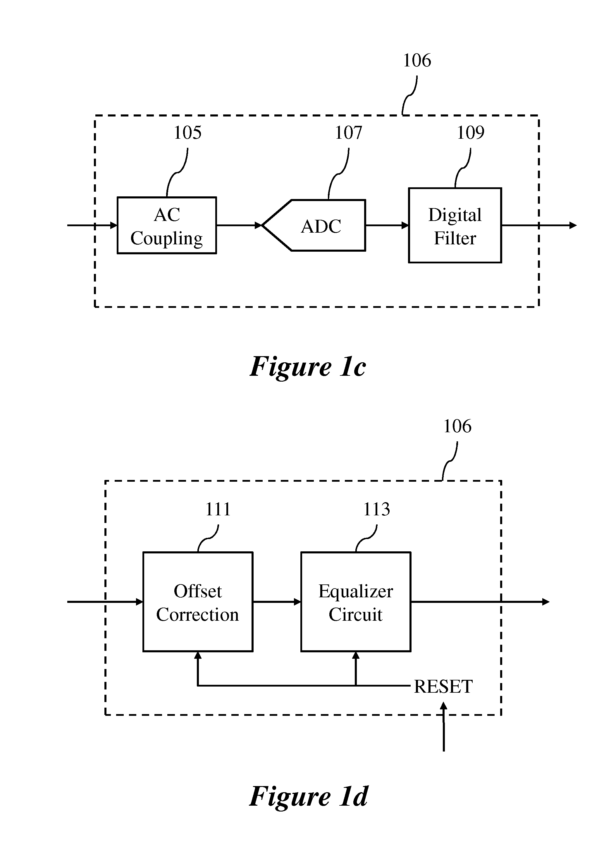
[0023]Description is made with respect to various embodiments in a specific context, namely pressure sensors, and more particularly, dynamic pressure sensors. Some of the various embodiments described herein include MEMS transducer systems, MEMS pressure sensors, pressure transducer and MEMS pressure transducer systems, dynamic MEMS pressure sensors, piezoelectric pressure sensors, and pressure sensor systems including dynamic and absolute pressure sensors. Example usage environments are presented for indoor navigation; however, such examples are in no way limiting. In other embodiments, aspects may also be appli...


PUM

PropertyMeasurementUnit
frequencyaaaaaaaaaa
frequencyaaaaaaaaaa
frequencyaaaaaaaaaa

Abstract

According to various embodiments, a dynamic pressure sensor includes a substrate, a reference volume formed in the substrate, a deflectable membrane sealing the reference volume, a deflection sensing element coupled to the membrane and configured to measure a deflection of the membrane, and a ventilation hole configured to equalize an absolute pressure inside the reference volume with an absolute ambient pressure outside the reference volume.

Description

TECHNICAL FIELD[0001]The present invention relates generally to sensor technologies, and, in particular embodiments, to a system and method for a dynamic pressure sensor.BACKGROUND[0002]Transducers that convert signals from one domain to another are often used in sensors. A common sensor that includes a transducer is a pressure sensor that converts pressure differences and / or pressure changes to electrical signals. Pressure sensors have numerous applications including, for example, atmospheric pressure sensing, altitude sensing, and weather monitoring.[0003]Microelectromechanical system (MEMS) based sensors include a family of transducers produced using micromachining techniques. MEMS, such as a MEMS pressure sensor, gather information from the environment by measuring the change of physical state in the transducer and transferring the signal to be processed by the electronics, which are connected to the MEMS sensor. MEMS devices may be manufactured using micromachining fabrication ...

Claims


Application Information

Patent Timeline
Patent Type & Authority Applications(United States)
IPC IPC(8): G01L9/00H04R1/08B81B3/00
CPCG01L9/0072B81B3/0021H04R2201/003B81B2201/0264H04R1/08G01L9/0073G01L9/0082G01L9/085B81B7/02G01L9/0042G01L9/0052G01L9/08
Inventor WIESBAUER, ANDREASDEHE, ALFONS
Owner INFINEON TECH AG
Why Eureka
Try Eureka