

Speckle free laser projection
- Summary
- Abstract
- Description
- Claims
- Application Information
AI Technical Summary
Benefits of technology
Problems solved by technology
Method used
Image

Examples
second embodiment
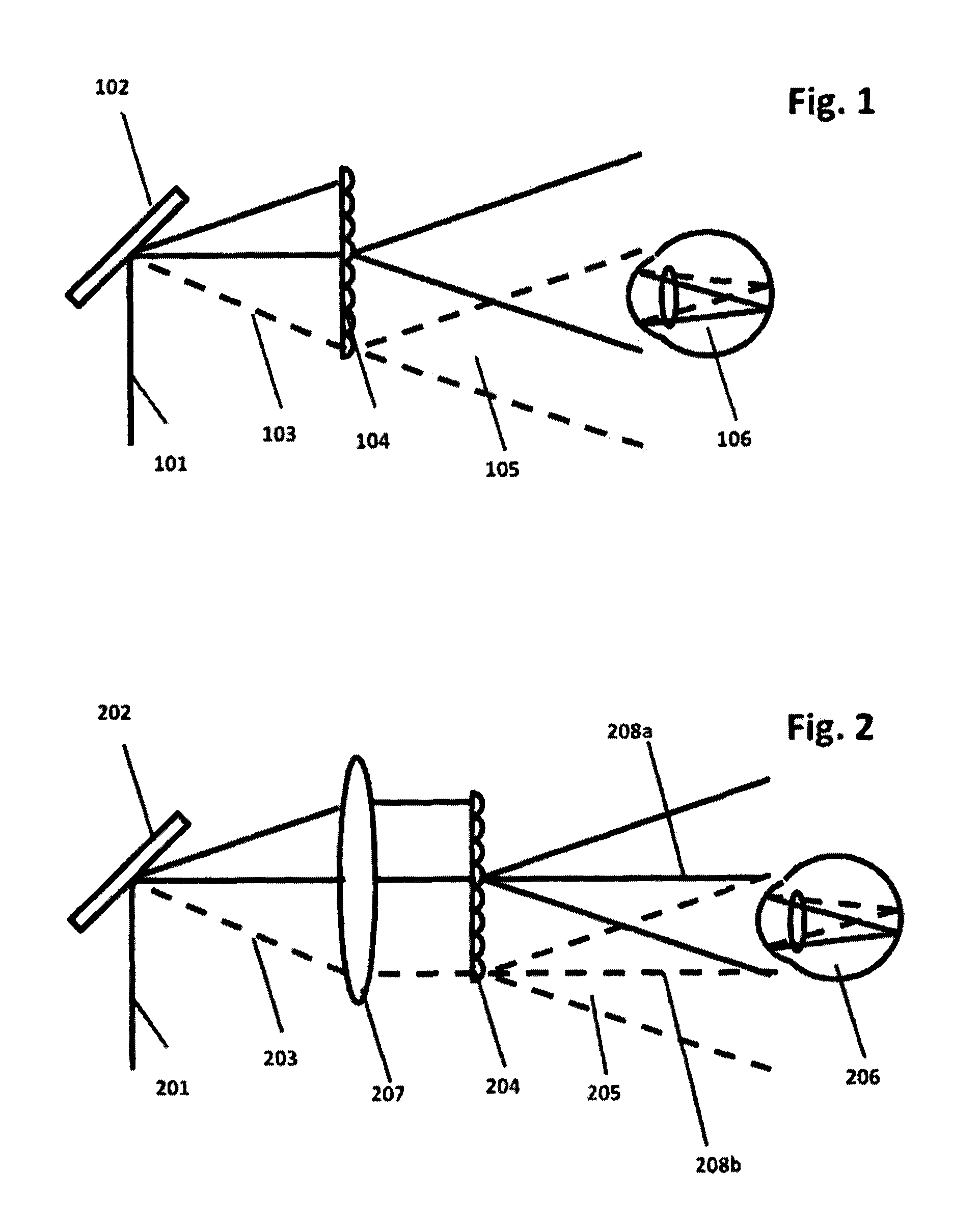
[0066]the present invention is shown in FIG. 2. This embodiment comprises:
[0067]A coherent light source 201 creating a non-disturbed wavefront. This can be a monochromatic or polychromatic source generated by one laser or multiple laser sources. An image generating light deflector 202 e.g. a scanning mirror, which deflects the light in one or two dimensions, generating a projection image 203. When the surface quality of the scanning mirror is good, the wavefront of the light of the projection image remains non-disturbed. The generated image is then directed onto a collimation optics 207 which directs the non-disturbed light onto a diffusive structure 204, in particular a microlens array.
[0068]The microlens array ideally has one microlens per pixel of the projection image. In this case, each pixel is matched to one microlens. Depending on the focal length of the microlenses, the light of each pixel is diverged into a particular angle creating a diffusive image 205. The diffusive imag...
third embodiment
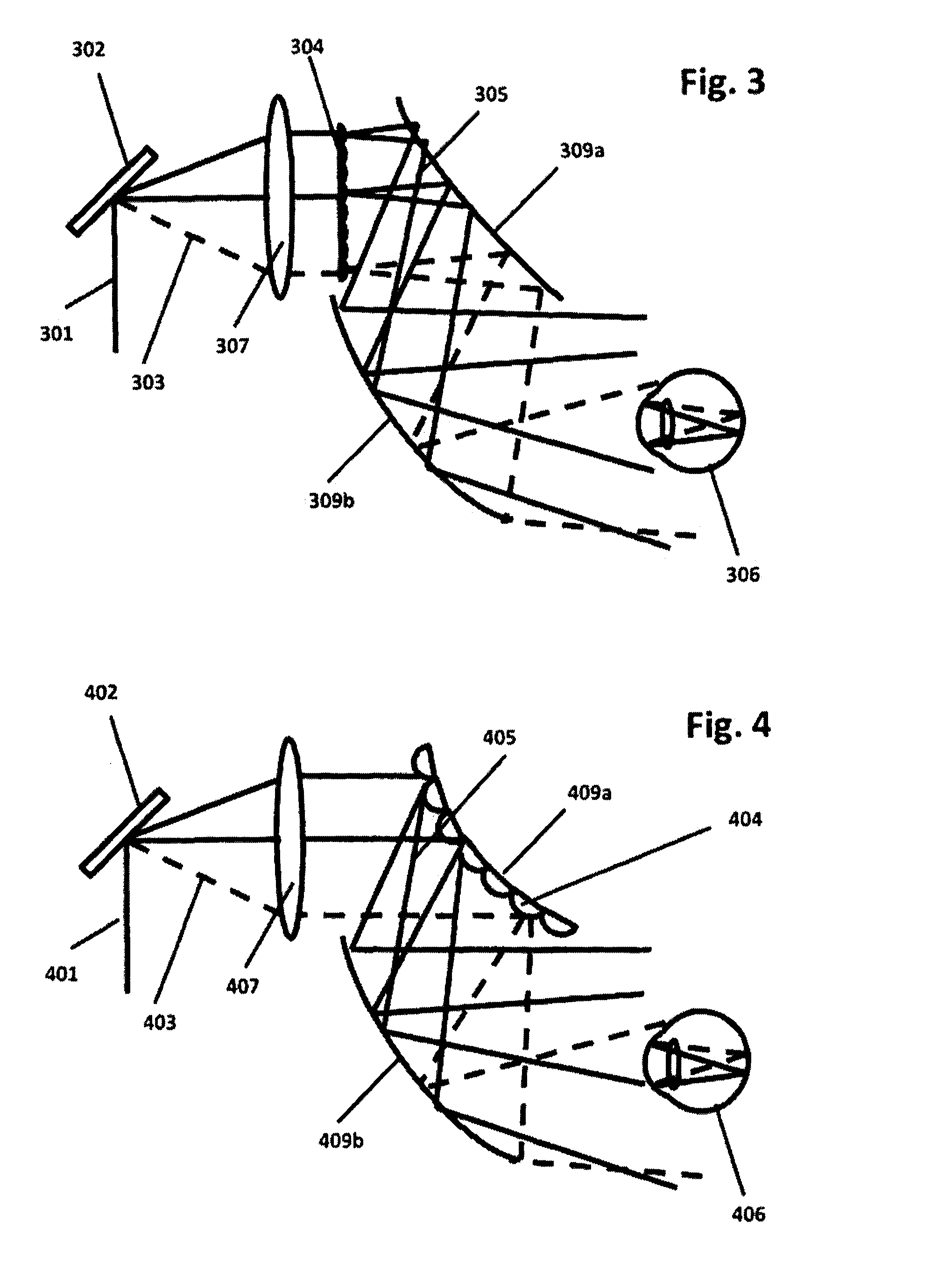
[0078]A forth embodiment of the present invention is shown in FIG. 4. This embodiment substantially corresponds to the third embodiment, with the exception that the diffusive structure 404 is integrated into the magnifying optics 409.
[0079]The invention is not limited to the microlens array described for the diffusive structure. Indeed, other structures could be defined for diffusing the light, while maintaining the non-disturbed wavefront of the light of each pixel and preventing any diffraction artifacts.
[0080]The invention also relates to systems in which the light deflector can be a two dimensional intensity modulating array such as a digital light processor (DLP) or an LCOS instead of a scanning mirror.
[0081]Some applications:
[0082]The optical system can be used in a large variety of applications, such as:[0083]Macro- and micro-projectors for home or professional displays[0084]Head-up displays[0085]Laptop / mobile projectors[0086]TV-projectors[0087]Business projectors[0088]Head-m...
PUM
 Abstract
Description
Claims
Application Information