Display apparatus and control method thereof
a technology of display apparatus and control method, which is applied in the direction of static indicating device, cathode-ray tube indicator, instruments, etc., can solve the problem that the conventional method cannot sufficiently reduce unevenness, and achieve the effect of reducing uneven brightness and chromaticity
- Summary
- Abstract
- Description
- Claims
- Application Information
AI Technical Summary
Benefits of technology
Problems solved by technology
Method used
Image
Examples
embodiment 1
[0043]A description will be given below of a light source device according to Embodiment 1 of the present invention. In Embodiment 1, an example of the case where the light source device is a backlight device used in a color image display apparatus will be described. However, the light source device is not limited to the backlight device used in a display apparatus. For example, the light source device may also be an illuminating device such as a street lamp or a room lamp.
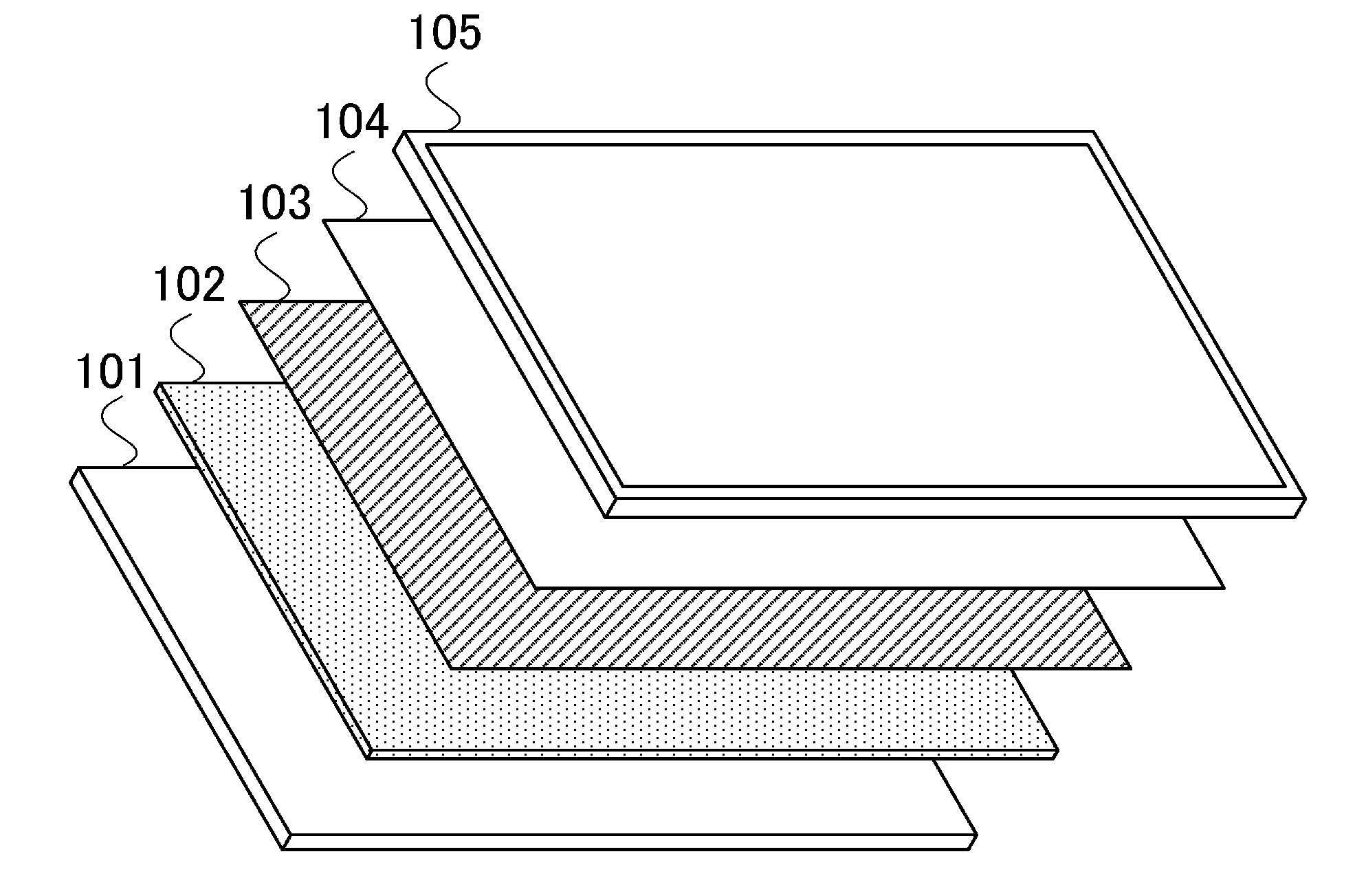
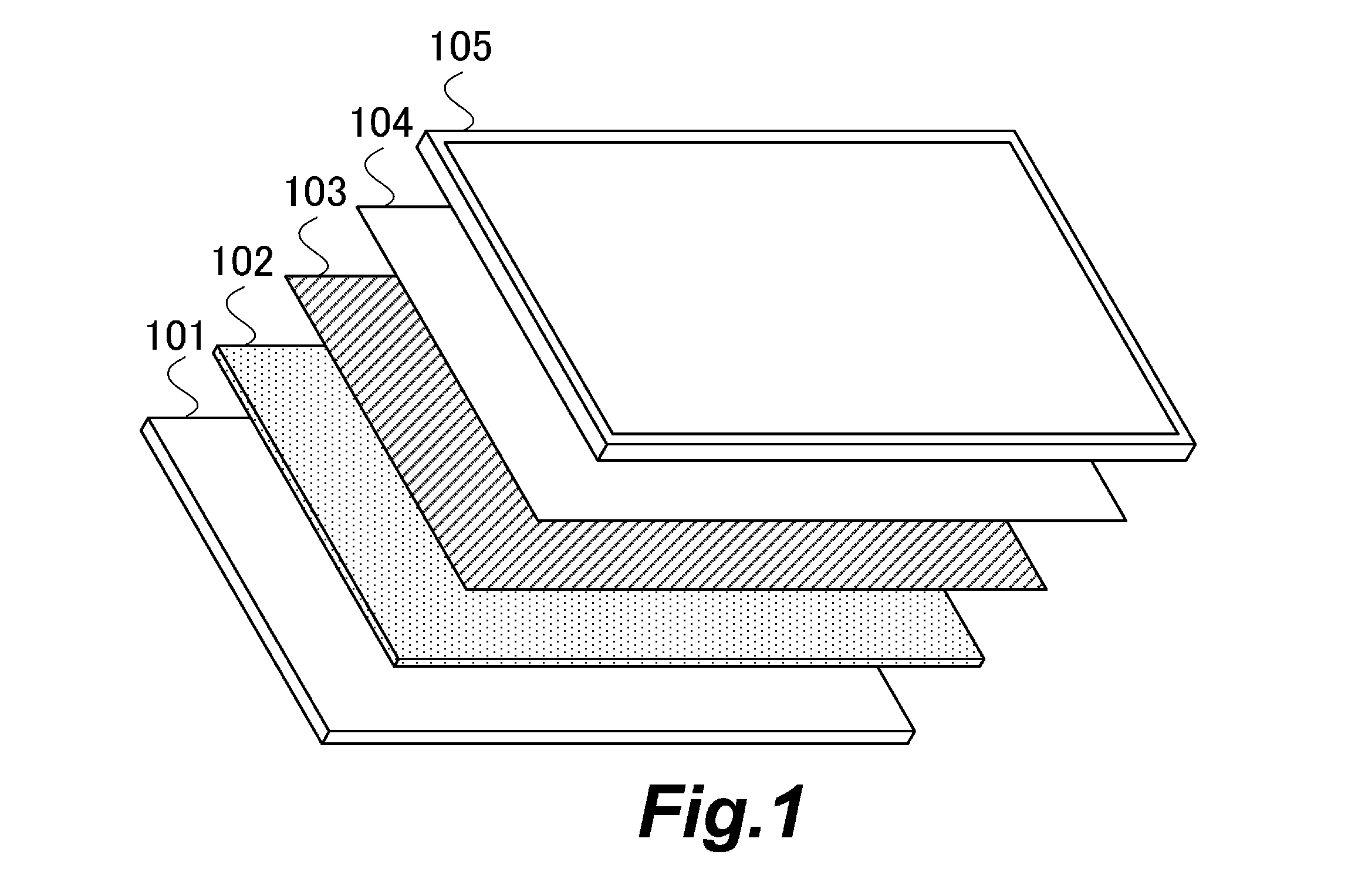
[0044]FIG. 1 is a schematic diagram showing an example of a configuration of the color image display apparatus according to Embodiment 1. The color image display apparatus has a backlight device, and a color liquid crystal panel 105. The backlight device has a light source board 101, a diffusion plate 102, a light focusing sheet 103, a reflection-type polarization film 104, and the like.
[0045]The light source board 101 emits light (white light) which illuminates the back surface of the color liquid crystal panel 1...
embodiment 2
[0135]A description will be given below of a light source device according to Embodiment 2 of the present invention. In Embodiment 1, one close optical sensor and one distant optical sensor are used. In Embodiment 2, a description will be given of an example of the case where a plurality of distant optical sensors is used. Note that the same members as used in Embodiment 1 are designated by the same reference numerals and a description thereof is omitted.
[0136]FIG. 16 is a schematic diagram showing the locations of a light emitting unit 300 used to detect the change of each of an individual brightness distribution and an individual color distribution, a close optical sensor S3, and distant optical sensors S4 when viewed in the front direction (from the color liquid crystal panel 105).
[0137]The microcomputer 125 uses, as the light emitting unit 300 used to detect the change of each of the individual brightness distribution and the individual color distribution, the light emitting uni...
PUM
 Abstract
Description
Claims
Application Information
 - R&D
- Intellectual Property
- Life Sciences
- Materials
- Tech Scout
- Unparalleled Data Quality
- Higher Quality Content
- 60% Fewer Hallucinations
Browse by: Latest US Patents, China's latest patents, Technical Efficacy Thesaurus, Application Domain, Technology Topic, Popular Technical Reports.
© 2025 PatSnap. All rights reserved.Legal|Privacy policy|Modern Slavery Act Transparency Statement|Sitemap|About US| Contact US: help@patsnap.com


