Display apparatus and control method thereof

a technology of display apparatus and control method, which is applied in the direction of static indicating device, cathode-ray tube indicator, instruments, etc., can solve the problem that the conventional method cannot sufficiently reduce unevenness, and achieve the effect of reducing uneven brightness and chromaticity

Inactive Publication Date: 2017-05-23
CANON KK
View PDF10 Cites 0 Cited by
  • Summary
  • Abstract
  • Description
  • Claims
  • Application Information

AI Technical Summary

Benefits of technology

[0009]To solve the problem, the present invention reduces the unevenness of brightness and chromaticity in a display apparatus including a backlight when discoloration, contamination, blur, or the like has occurred in the optical member forming the backlight due to aging.
[0022]According to the present invention, in a display apparatus including a backlight, unevenness in brightness and chromaticity can be reduced when discoloration, contamination, blur, or the like has occurred in the optical member forming the backlight due to aging.

Problems solved by technology

This causes a problem in that the conventional method cannot sufficiently reduce the unevenness.

Method used


Image

  • Display apparatus and control method thereof
  • Display apparatus and control method thereof
  • Display apparatus and control method thereof

Examples


embodiment 1

[0042]A description will be given below of a light source device according to Embodiment 1 of the present invention. In Embodiment 1, an example of the case where the light source device is a backlight device used in a color image display apparatus will be described. However, the light source device is not limited to the backlight device used in a display apparatus. For example, the light source device may also be an illuminating device such as a street lamp or a room lamp.

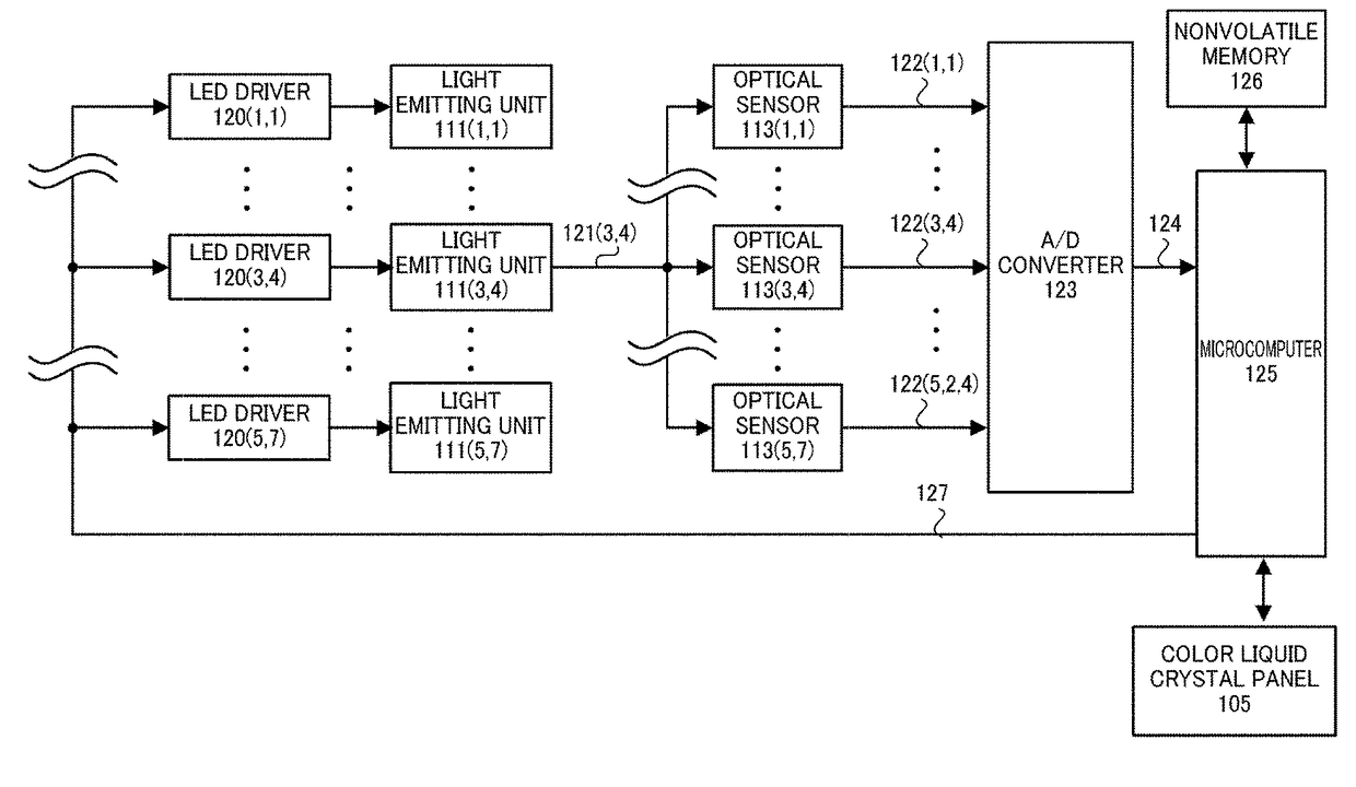
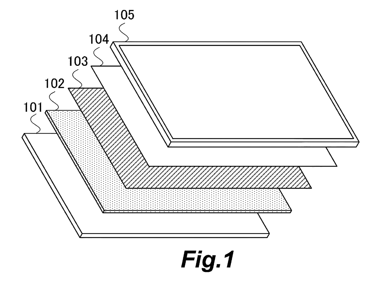
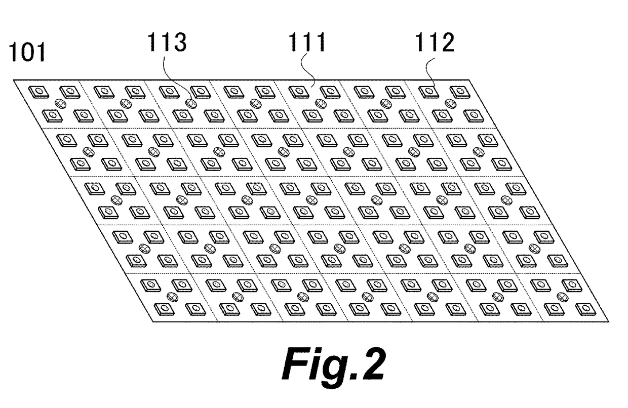
[0043]FIG. 1 is a schematic diagram showing an example of a configuration of the color image display apparatus according to Embodiment 1. The color image display apparatus has a backlight device, and a color liquid crystal panel 105. The backlight device has a light source board 101, a diffusion plate 102, a light focusing sheet 103, a reflection-type polarization film 104, and the like.

[0044]The light source board 101 emits light (white light) which illuminates the back surface of the color liquid crystal panel 1...

embodiment 2

[0134]A description will be given below of a light source device according to Embodiment 2 of the present invention. In Embodiment 1, one close optical sensor and one distant optical sensor are used. In Embodiment 2, a description will be given of an example of the case where a plurality of distant optical sensors is used. Note that the same members as used in Embodiment 1 are designated by the same reference numerals and a description thereof is omitted.

[0135]FIG. 16 is a schematic diagram showing the locations of a light emitting unit 300 used to detect the change of each of an individual brightness distribution and an individual color distribution, a close optical sensor S3, and distant optical sensors S4 when viewed in the front direction (from the color liquid crystal panel 105).

[0136]The microcomputer 125 uses, as the light emitting unit 300 used to detect the change of each of the individual brightness distribution and the individual color distribution, the light emitting uni...


PUM


Abstract

Provided is a display apparatus including: a light emitting unit having a light source; a display unit configured to display an image by controlling a transmittance of light from the light emitting unit; first and second sensors provided in the light emitting unit to detect a brightness of the light source; and a control unit configured to control a transmittance of the display unit on the basis of detection values from the first and second sensors. A distance from the light source to the second sensor is longer than a distance from the light source to the first sensor. The control unit controls the transmittance of the display unit on the basis of a change degree of the detection value from the first sensor during a given period and a change degree of the detection value from the second sensor during the period.

Description

BACKGROUND OF THE INVENTION[0001]Field of the Invention[0002]The present invention relates to a display apparatus and a control method thereof.[0003]Description of the Related Art[0004]Some examples of color image display apparatuses include a color liquid crystal panel having a color filter, and a light source device (backlight device) which illuminates the back surface of the color liquid crystal panel with white light. Conventionally, as the light source of a light source device, a fluorescent lamp such as Cold Cathode Fluorescent Lamp (CCFL) has been used mainly. However, recent years have seen an increased use of a light emitting diode (LED), which is excellent in terms of power consumption, lifetime, color reproducibility, and environmental load, as the light source of a light source device.[0005]In general, a light source device (LED backlight device) using an LED as a light source has a large number of LEDs. Japanese Patent Application Laid-open No. 2001-142409 discloses an ...

Claims


Application Information

Patent Timeline
Patent Type & Authority Patents(United States)
IPC IPC(8): G09G5/02G09G3/34
CPCG09G3/3426G09G3/3413G09G2320/0242G09G2320/048G09G2360/145
Inventor KURITA, MASANAO
Owner CANON KK
Why Eureka
Try Eureka