Color purity improving sheet, optical apparatus, image display, and liquid crystal display

Inactive Publication Date: 2008-09-04
NITTO DENKO CORP
View PDF14 Cites 26 Cited by
  • Summary
  • Abstract
  • Description
  • Claims
  • Application Information

AI Technical Summary

Benefits of technology

[0018]The first and second color purity improving sheets of the present invention each are not provided for a component, such as a light guide plate or a light reflector, as in a conventional optical apparatus. They are independent sheets. Since the sheets of the present invention each are an independent sheet as described above, a light-emitting means can be distributed uniformly inside a sheet (a light-emitting layer). Accordingly, the sheets of the present invention can improve the color purity of light that passes therethrough while preventing unevenness in color and brightness from occurring. Furthermore, in the first and second color purity improving sheets of the present invention, the surface of the light-emitting layer or surface-roughened layer on at least the light outgoing side is roughened

Problems solved by technology

In the conventional liquid crystal display, however, colors between any two of R, G, and B (for instance, yellow light in the wavelength range between the wavelength range of R and the wavelength range of G, and light in the wavelength range between the wavelength range of G and the wavelength range of B) other than R, G, and B are mixed in the emission spectrum of a cold cathode tube, and they are not filtered out sufficiently with color filters.
As a result, there has been a problem in that the color reproducibility deteriorates in the display image quality.
Furthermore, when an LED corresponding to three colors of R, G, and B is used as a backlight, excellent color reproducibility is obtained, but there has been a problem in that the control circuit is complicated and higher cost is required.
However, in the method in which a light guide plate or a light reflector is allowed to cont

Method used


Image

  • Color purity improving sheet, optical apparatus, image display, and liquid crystal display
  • Color purity improving sheet, optical apparatus, image display, and liquid crystal display
  • Color purity improving sheet, optical apparatus, image display, and liquid crystal display

Examples


example 1

Production of Color Purity Improving Sheet

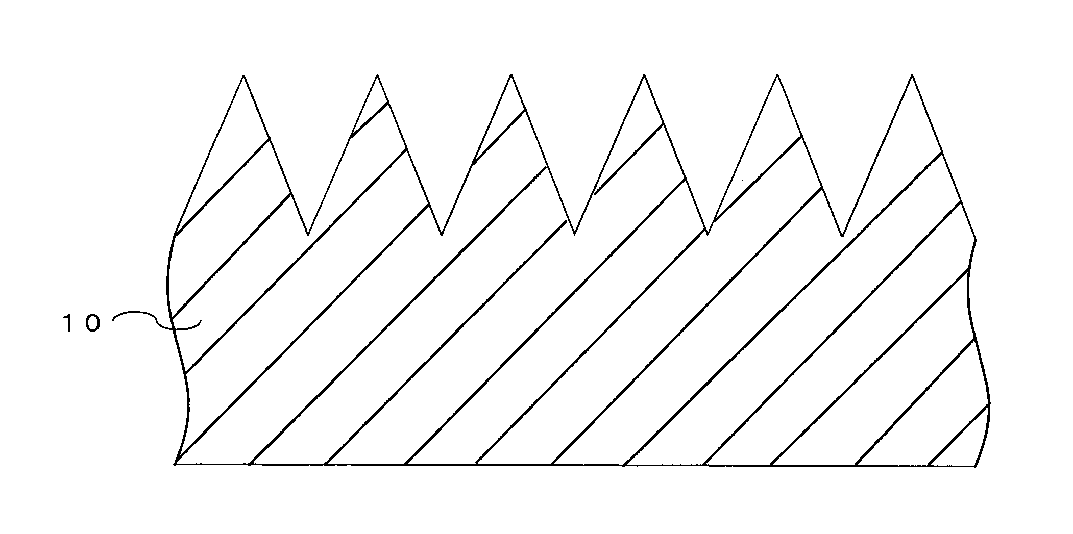
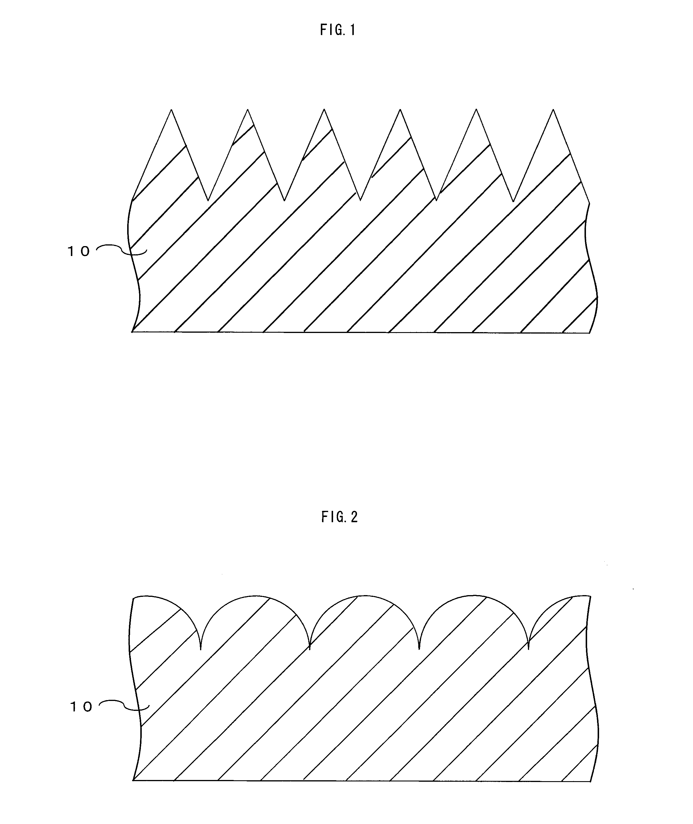
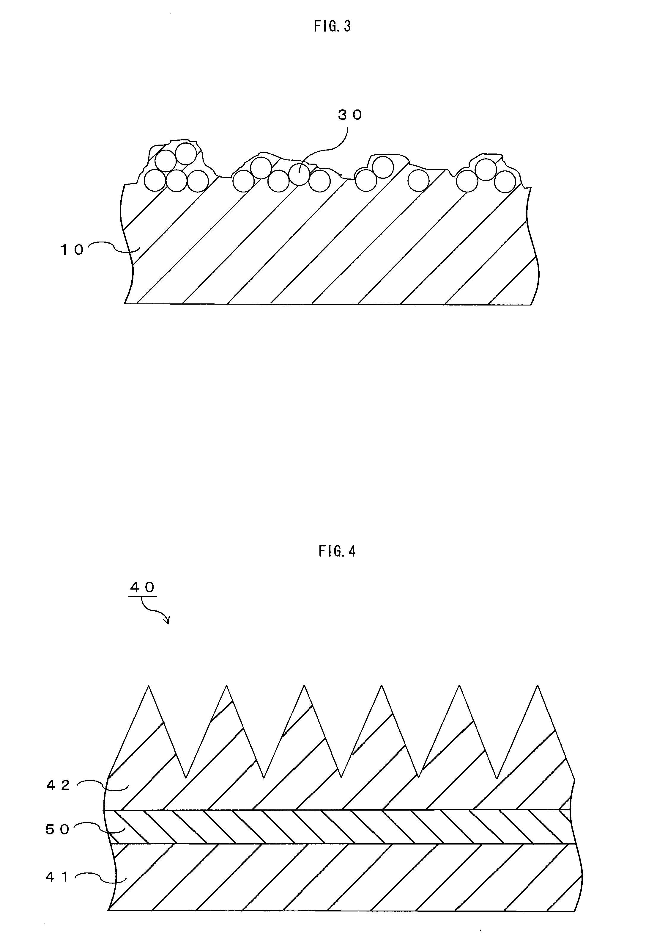
[0070]A fluorescent material (manufactured by BASF A.G., “Lumogen F Red 305” (trade name)) having the structure represented by Formula (1) above was added to and dissolved in a 30% by weight toluene solution of polymethylmethacrylate so as to be 0.19% by weight with respect to polymethylmethacrylate. This solution was applied onto a polyethylene terephthalate (PET) film base with an applicator to form a coating film, which was then dried at 80° C. for 30 minutes. Thus a film was obtained. After being dried, the film was separated from the PET film base and thereby a 30-μm thick polymethylmethacrylate film was obtained. One surface (the surface on the light outgoing side) of the film obtained above was subjected to a surface grinding process using a sandpaper (#100), so that the color purity improving sheet of this example was obtained. The surface located on the light outgoing side of the color purity improving sheet had an arithmetic averag...

example 2

[0071]A color purity improving sheet of this example was obtained in the same manner as in Example 1 except that the surface grinding process was performed using a sandpaper (#700). The surface located on the light outgoing side of the color purity improving sheet had an arithmetic average surface roughness Ra of 0.13 μm.

example 3

[0072]A color purity improving sheet of this example was obtained in the same manner as in Example 1 except that the surface grinding process was performed using a sandpaper (#800). The surface located on the light outgoing side of the color purity improving sheet had an arithmetic average surface roughness Ra of 0.15 μm.


PUM

PropertyMeasurementUnit
Lengthaaaaaaaaaa
Wavelengthaaaaaaaaaa
Surface roughnessaaaaaaaaaa

Abstract

The present invention provides a highly practicable color purity improving sheet that while preventing unevenness in color and brightness from occurring, allows light with an improved color purity to be used for an image display efficiently and can improve color reproducibility of the image display. The color purity improving sheet includes a light-emitting layer which improves the purity of a color in a target wavelength range by absorbing light in a specific wavelength range other than the target wavelength range and converts the absorbed light to emitted light in the target wavelength range. The surface of the light-emitting layer on at least the light outgoing side is roughened so as to have an arithmetic average surface roughness Ra defined in JIS B 0601 (1994 version) in the range of 0.1 to 100 μm.

Description

CROSS-REFERENCE TO RELATED APPLICATIONS[0001]This application claims priority from Japanese Patent Application No. 2007-14751, filed on Jan. 25, 2007. The entire subject matter of the Japanese Patent Application is incorporated herein by reference.BACKGROUND OF THE INVENTION[0002]1. Field of the Invention[0003]The present invention relates generally to color purity improving sheets, optical apparatuses, image displays, and liquid crystal displays.[0004]2. Description of the Related Art[0005]Recently, a liquid crystal display in which light emitted from a light source device such as a cold cathode tube or a light emitting diode (LED) is controlled by a liquid crystal panel and images formed thereby have been studied and put into practical use. In the liquid crystal display, in order to distribute the light from the light source device over the whole display surface equally, a light guide plate is disposed on the optical path reaching the light source device and in parallel with the l...

Claims


Application Information

Patent Timeline
IPC IPC(8): C09K19/02B32B3/28
CPCC09B5/62C09K11/06C09K2211/1029G02B5/021G02B5/0278G02B5/045Y10T428/10G02B6/0051G02B6/0053G02F2001/133607G02F2001/133614Y10T428/24364G02B6/0038C09K2323/00G02F1/133607G02F1/133614F21S8/085F21S13/10F21W2111/02H02B1/26Y02B20/72
Inventor NAGASAWA, MEGUMUSAKAMOTO, MICHIEOOTANI, AKIRA
Owner NITTO DENKO CORP
Why Eureka
Try Eureka