Calculating Latency in Computer Networks

a technology of computer networks and latency calculation, applied in the field of computer networks, can solve problems such as preventing implementation, affecting the purpose of measurement, and consuming resources,

Active Publication Date: 2015-10-01
CISCO TECH INC
View PDF17 Cites 54 Cited by
  • Summary
  • Abstract
  • Description
  • Claims
  • Application Information

AI Technical Summary

Problems solved by technology

In addition, injecting traffic into the network for the purposes of measuring the performance parameters of the network often proves to be performance impacting and may defeat the purpose of the measurements.
This arrangement may be resource intensive

Method used


Image

  • Calculating Latency in Computer Networks
  • Calculating Latency in Computer Networks
  • Calculating Latency in Computer Networks

Examples


example embodiments

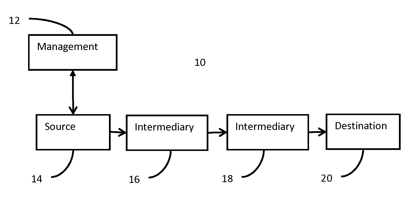
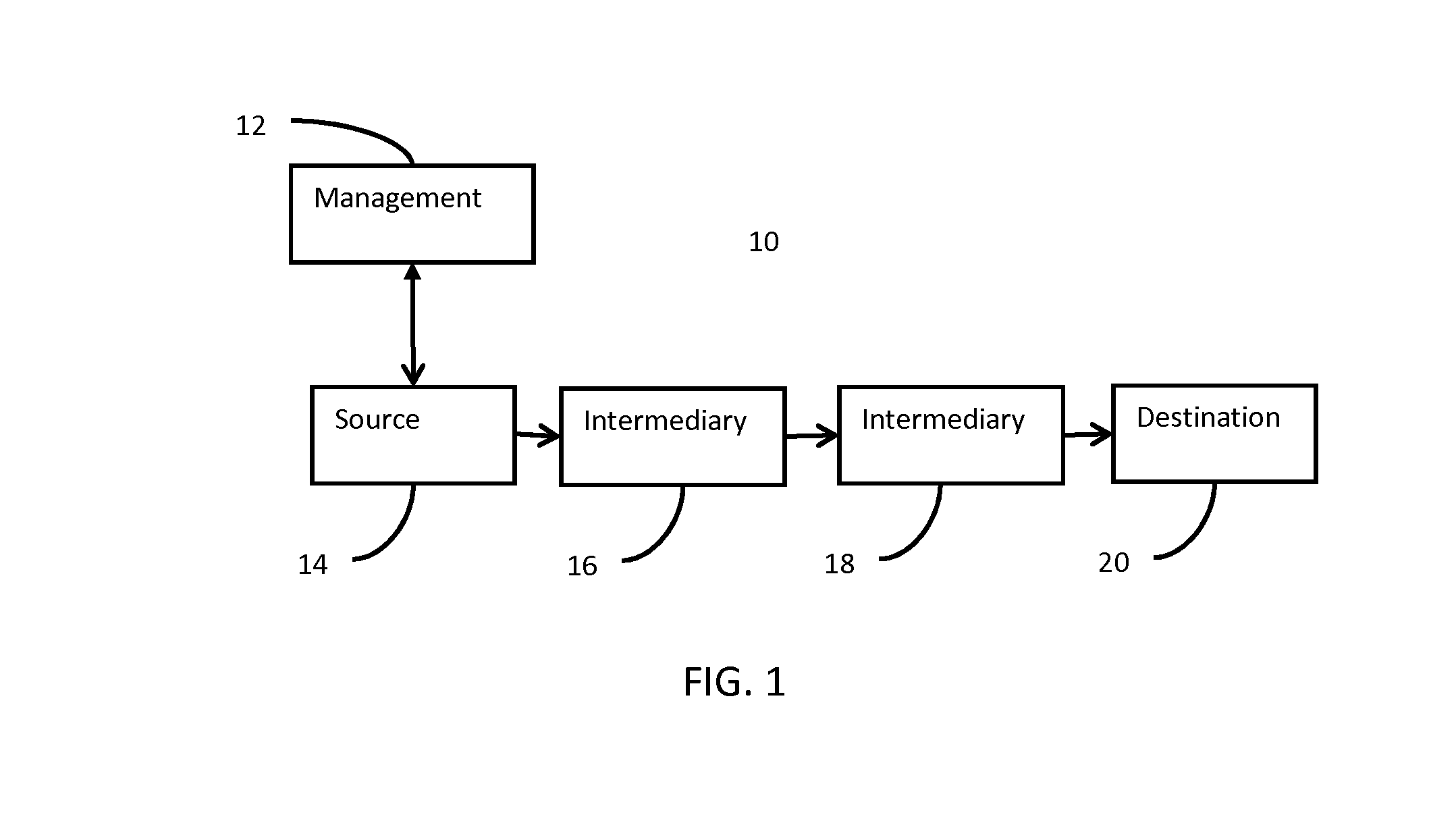
[0012]Some measures of latency use synthetic traffic (i.e., response to protocol packets used for management instead of the native (user-generated) traffic). With the usage of quality of service (QoS), and advanced traffic selection technologies, such as medianet metadata or deep packet inspection / network based application recognition (DPI / NBAR), the difference in network treatment of synthetic traffic (i.e., fake traffic) and actual or user traffic is getting wider and wider. In addition, injecting traffic into the network for the purposes of measuring the performance parameters of the network often proves to be performance impacting and may defeat the purpose of the measurements.

[0013]OWD may require a pre-determined traffic selector and monitoring infrastructure. NetFlow exports to the NetFlow collector, but the out-of-flow NetFlow collector must understand network topology. This arrangement may be resource intensive and pre-planning is needed. This type of deployment overhead ma...


PUM


Abstract

In one implementation, data is communicated along a communications route in a network. A mediatrace request is generated for the communications route. Responses to the mediatrace request are received from along the communications route. The hop-by-hop latency is passively measured, from the responses, with one-way delay along the communications route in the network.

Description

TECHNICAL FIELD[0001]This disclosure relates in general to computer networks, and more particularly to calculating latency calculation in computer networks.BACKGROUND[0002]A computer network path may be formed from multiple layer 2 (L2) and layer 3 (L3) hops. Each leg or hop and corresponding node may contribute to latency and jitter. There have been various methods (e.g., Internet Control Message Protocol (ICMP) pings or Internet Protocol Service Level Agreement (IPSLA) probes) to measure path latency and / or nodal latency. For these methods, synthetic traffic is used. Rather than using the user data (e.g., audio or video), requests or packets generated for management or to measure latency are used. For example, utilities, such as traceroute and path ping, are available for displaying a route of a packet across a network. Successive protocol packets are sent across the network with varying hop limits. Return messages produce a list of routers that the packets have traversed. Timesta...

Claims


Application Information

Patent Timeline
IPC IPC(8): H04L12/26
CPCH04L43/106H04L43/0858
Inventor AKHTER, AAMERNEDELTCHEV, PLAMENPIGNATARO, CARLOS M.
Owner CISCO TECH INC
Why Eureka
Try Eureka