Tape cartridge

a technology of tape cartridges and tapes, applied in typewriters, instruments, printing, etc., can solve the problems of complex operation and complicated structure of this portion

Active Publication Date: 2015-10-08
SEIKO EPSON CORP
View PDF1 Cites 25 Cited by
  • Summary
  • Abstract
  • Description
  • Claims
  • Application Information

AI Technical Summary

Benefits of technology

[0021]According to this configuration, the platen roller can reliably move to the restraint canceling position when the tape cartridge is ins

Problems solved by technology

This results in the problem that the structure of this portion becomes complicated.
Therefore, it is required to rise and fall the interval restr

Method used


Image

  • Tape cartridge
  • Tape cartridge
  • Tape cartridge

Examples


Embodiment Construction

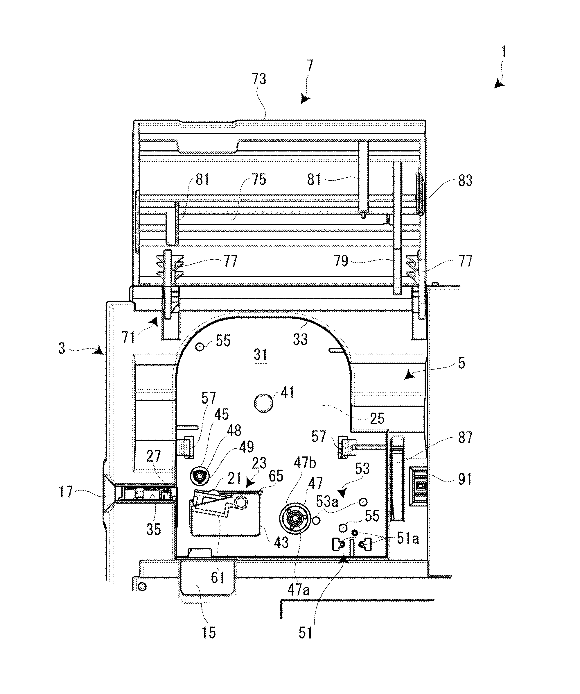
[0031]Hereinafter, a description will be given, with reference to the accompanying drawings, of a tape cartridge according to an embodiment of the present invention in conjunction with a tape printing apparatus in which the tape cartridge is installed. The tape printing apparatus is used to perform printing while feeding out a printing tape and an ink ribbon from the installed tape cartridge and cut off a printed part of the printing tape to create a label (tape piece).

[0032][Outline of Tape Printing Apparatus]

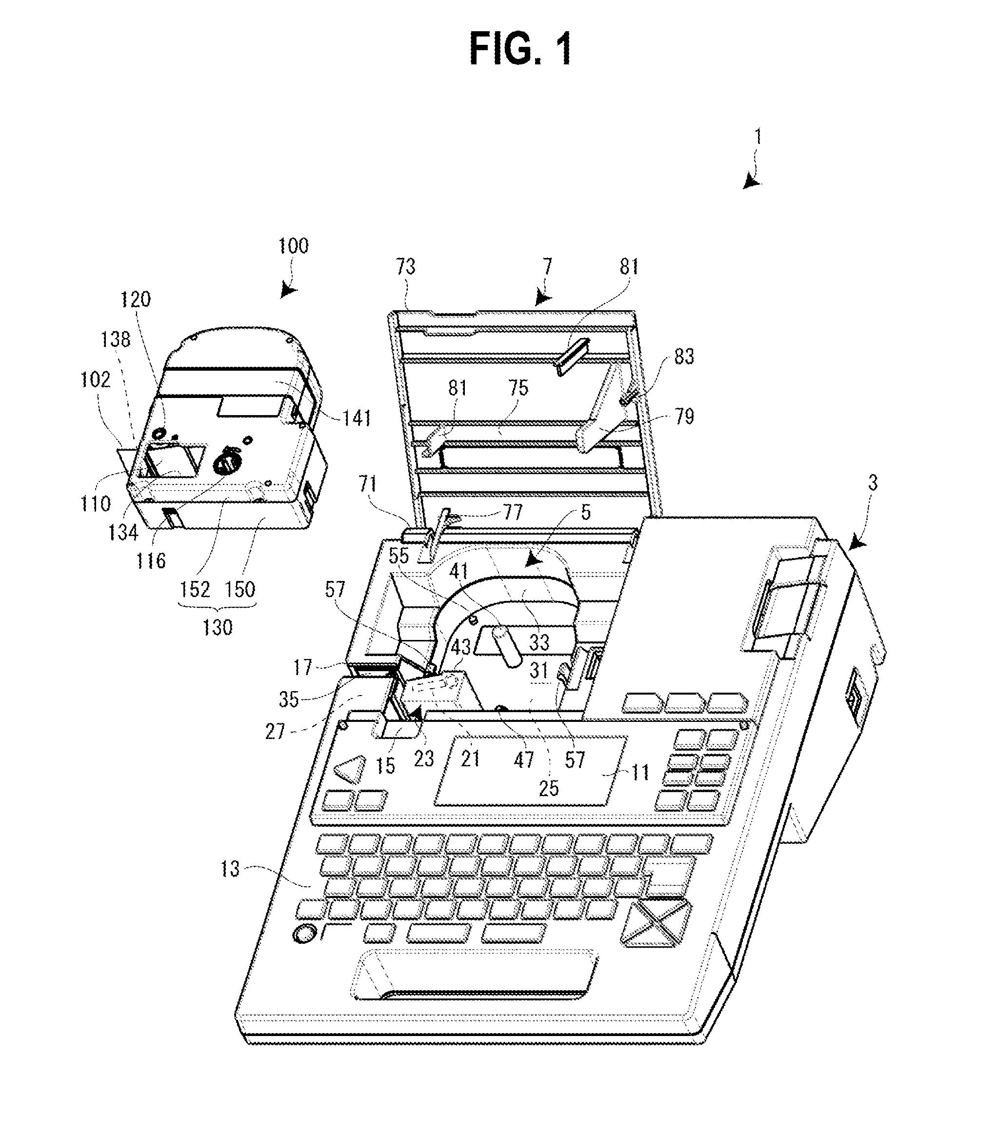
[0033]FIG. 1 is an external perspective view of the tape printing apparatus and the tape cartridge installed in the tape printing apparatus. As shown in FIG. 1, a tape printing apparatus 1 includes an apparatus casing 3 constituting an outer shell, a cartridge installation portion 5 on which a tape cartridge 100 is detachably installed, and an opening / closing cover 7 used to open / close the cartridge installation portion 5. At the upper surface of the apparatus casing 3, the ca...


PUM


Abstract

A tape cartridge is detachably installed on a cartridge installation portion of a tape printing apparatus having a platen supporting shaft and a printing head, a base end of the platen supporting shaft being fixed to the cartridge installation portion at one end of the platen supporting shaft and extending in an attaching/detaching direction of the tape cartridge. The tape cartridge has a platen roller through which the platen supporting shaft passes when the tape cartridge is installed on the cartridge installation portion and which receives a pressing force from the printing head when a printing operation is performed in a state in which the tape cartridge is installed on the cartridge installation portion, and a fitting portion in which a tip end of the platen supporting shaft passing through the platen roller fits when the tape cartridge is installed on the cartridge installation portion.

Description

CROSS REFERENCE TO RELATED APPLICATION[0001]This application is a continuation of PCT application No. PCT / JP2015 / 058317, which was filed on Mar. 19, 2015 based on Japanese Patent Application No. 2014-060916 filed on Mar. 24, 2014, the contents of which are incorporated herein by reference.BACKGROUND[0002]1. Technical Field[0003]The present invention relates to a tape cartridge installed on the cartridge installation portion of a tape printing apparatus to be used and subjected to printing by the tape printing apparatus.[0004]2. Background Art[0005]Up until now, a tape cassette installed in a printing apparatus to be used has been known as such a tape cartridge. See Japanese Patent No. 3629823.[0006]The tape cassette includes a tape supplying reel on which a printing tape is wound, a ribbon supplying reel on which an ink ribbon is wound, a ribbon winding-up reel that winds up the ink ribbon, and a cassette casing that accommodates these constituents.[0007]On the other hand, the print...

Claims


Application Information

Patent Timeline
IPC IPC(8): B41J32/00B41J3/407
CPCB41J3/4075B41J32/00B41J15/044B41J35/28B41J11/04B41J2/325B41J32/02B41J2202/31
Inventor SAKANO, HIDEKI
Owner SEIKO EPSON CORP
Why Eureka
Try Eureka