Non-rubbing gate valve for semiconductor fabrication apparatus

a technology of semiconductor fabrication apparatus and gate valve, which is applied in the direction of valve details, valve arrangement, valve operating means/release devices, etc., can solve the problems of o-ring distortion, structure assumes complexity, and increases the cost, so as to reduce the size, reduce the size, and reduce the effect of rotational motion

Active Publication Date: 2006-09-05
KITZ SCT
View PDF11 Cites 22 Cited by
  • Summary
  • Abstract
  • Description
  • Claims
  • Application Information

AI Technical Summary

Benefits of technology

[0020]According to the first aspect of the invention, upon opening and closing of the valve, a force which is imposed in a direction that causes a sealed portion to be rubbed with a valve seat is not generated. Therefore, a seal member is not distorted and generation of particles is suppressed, thereby exhibiting an excellent sealing property, and there is no risk the seal member being dropped out. In addition, excellent sealing property is reliably maintained over a long period of time even if opening and closing operations of the valve are repeatedly carried out.
[0022]According to the fourth aspect of the invention, rectilinear motion of the valve rod is efficiently converted to rotational motion by actuating the movement operation mechanism, and a great thrust for sealing the valve can be generated. For example, when a screw having a pitch of 60 mm and a lead angle of 45 degree is moved by 15 mm to convert the movement of the valve body in the direction orthogonal to the movement of the valve rod to 2 mm, a thrust 7.5 times the thrust of the movement operation mechanism can be obtained (excluding a screw efficiency), thereby providing a gate valve which is reduced in size and exhibits excellent durability.
[0023]According to the fifth aspect of the invention, reciprocation movement of the movement operation mechanism enables the valve rod to be reliably moved and rotated. The movement and rotation of the valve rod enables the valve body to be smoothly and stably moved.
[0024]According to the sixth aspect of the invention, distortion of the sealed portion is infallibly prevented, and the movement of the valve body during the course of opening or closing the valve is moderated to thereby suppress adverse effects on the sealed portion to a minimum possible level. No additional cylinder is required, and the cylinder that moves the valve rod may be used without giving any modification thereto to enable a highly efficient conversion. In addition, since the gate valve body is landed softly upon opening and closing of the gate valve body, generation of particles is suppressed to a minimum possible level.
[0025]According to the seventh aspect of the invention, when closing the valve, sealing is attained at the bottom dead center of the eccentric cam. Even when clamping force exerted on the valve body seal material or thrust generated by inverse pressure to the valve body is imposed on the valve rod, such force is not converted to force that would rotate the valve rod reverse. Therefore, valve-sealing function is maintained even when stooping feed of air to the cylinder. The thrust at the sealing portion and valve seat is maintained at a constant level to maintain sealing is at all times with appropriate thrust. Thus, an excellent sealing property is obtained. In addition, upon opening the valve, no spring is required in order to pull the valve body away. The valve body is reliably pulled away by means of the eccentric cam. Therefore, the valve body is reliably opened and closed without causing any distortion in the valve body seal material even when the seal material assumes adhesiveness.
[0026]According to the eighth aspect of the invention, the bellows can be displaced following the movement of the gate valve body to attain reliable sealing from outside, and the mechanism section, such as an eccentric cam, can be incorporated in the valve body. Therefore generation of particles are suppressed to a minimum possible level. In addition, plural bellows are not required because of the structure that moves the valve body in a direction orthogonal to the valve rod. Therefore, the structure contributes to reduction of the size and cost and makes the assemblage easy.

Problems solved by technology

However, the structure assumes complexity due to the existence of increased number of cylinder structure to thereby elevate the cost, which is problematic.
This applies force to an O-ring, which is provided at the valve body for sealing, in a direction to cause distortion of the O-ring, which is problematic.
Meanwhile, in the course of rotation of the valve body for opening the valve, force is applied to the O-ring in a direction causing distortion thereof in the same manner as in the case of closing the valve.
In such cases, greater force that causes distortion is applied to the O-ring, resulting in possible dropout of the O-ring.
As described above, the prior art gate valves fail to achieve a target object to provide non-rubbing gate valves, and great distortion force is applied to the O-ring upon either opening or closing the valve.
Thus, particles are readily generated, the product service life becomes short, and there is a possibility of the O-ring being dropped out.
Accordingly, the structure of the displacement mechanism tends to be complex and large in size.

Method used


Image

  • Non-rubbing gate valve for semiconductor fabrication apparatus
  • Non-rubbing gate valve for semiconductor fabrication apparatus
  • Non-rubbing gate valve for semiconductor fabrication apparatus

Examples


Embodiment Construction

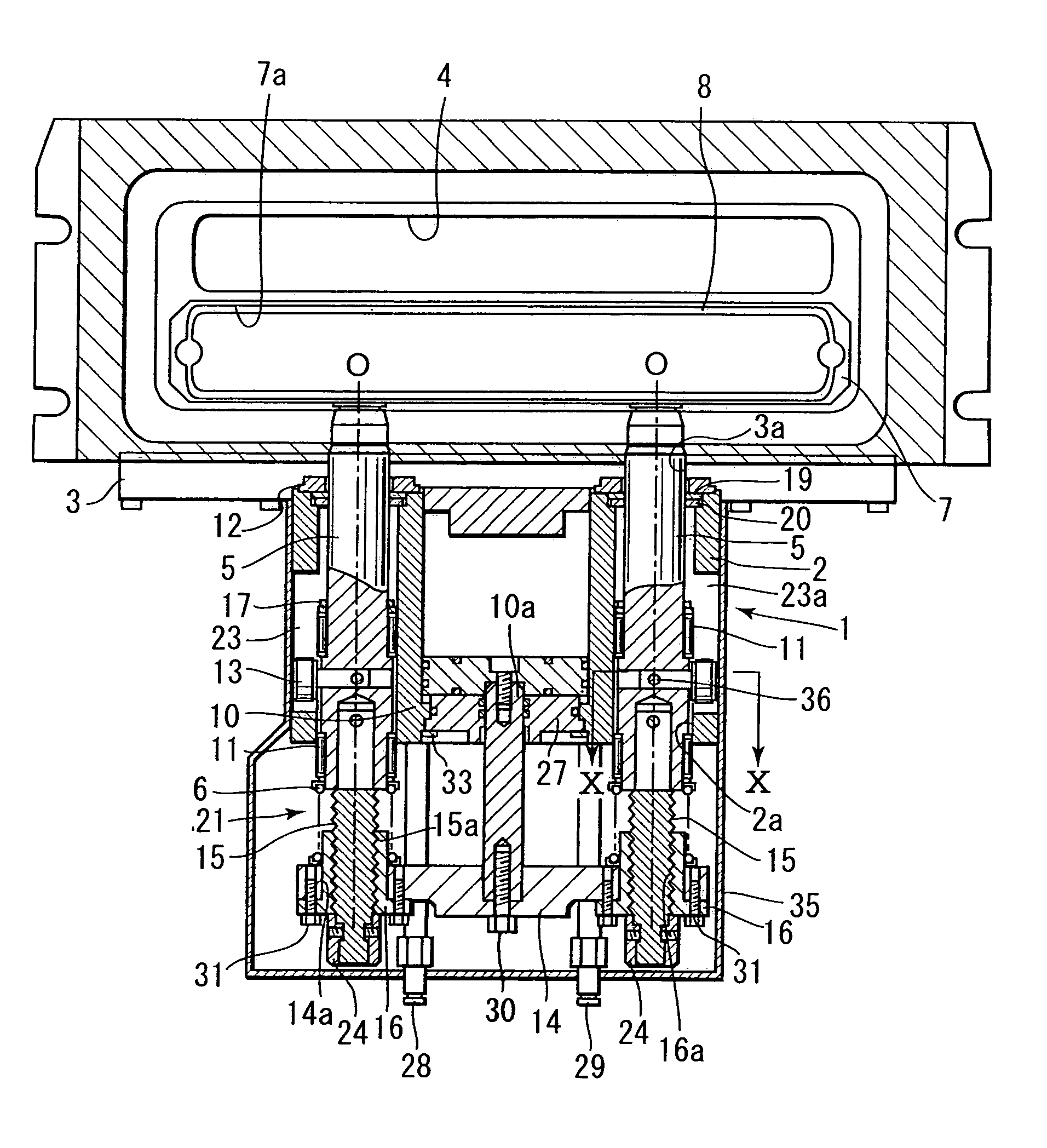
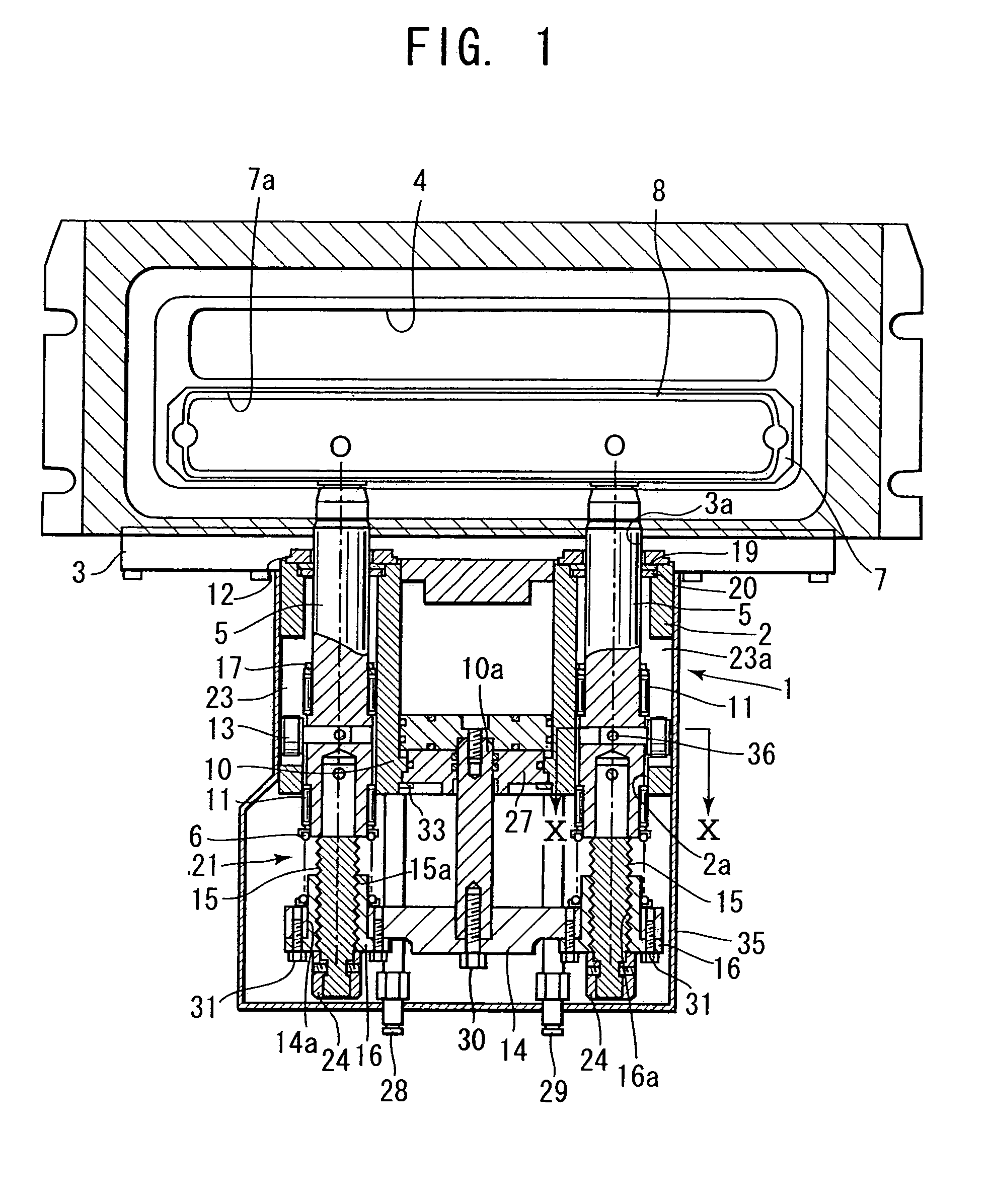
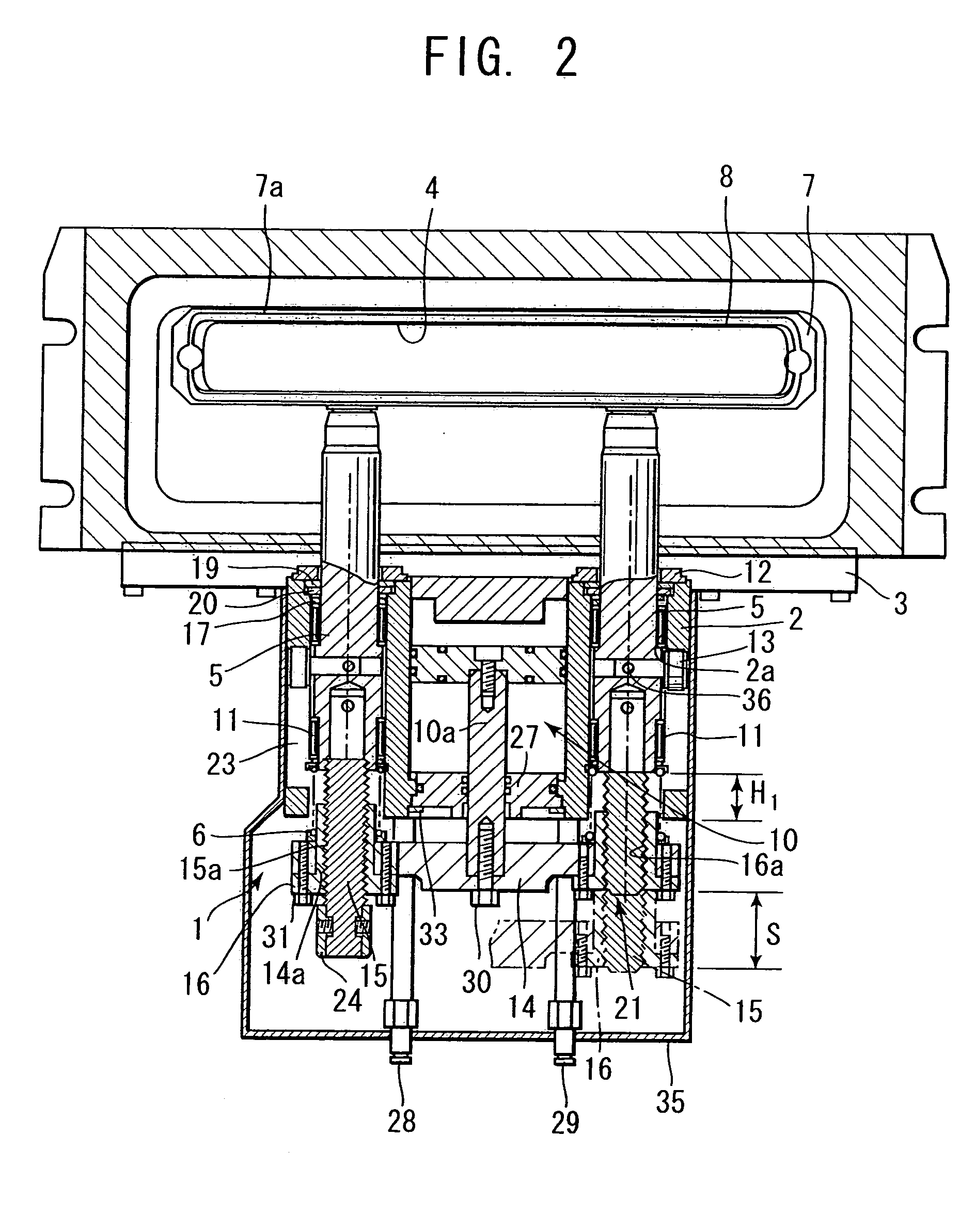
[0039]The present invention will be described in detail using embodiments of a gate valve with reference to the accompanying drawings. In the embodiment shown in FIG. 1 through FIG. 5, a valve main body 1 comprises, for example, an actuator or a cylinder housing, and forms the entirety of a gate valve of the present invention. A housing 2 is a structure provided therein with a movement operation mechanism 10 and a rotating motion mechanism 21 that will be described later. A body 3 serving as a bonnet is fixedly provided at the upper portion of the housing 2 in a fashion integral with the housing. A flow passage port 4 is formed at a position above the front side of the body 3. The flow passage port 4 may be provided as a chamber insert in a chamber. In this case, the port may be provided as integrated with the chamber.

[0040]In a modification, the body 3 may be separated from the housing 2. In another modification, the flow passage port may be formed at a position below the front sid...


PUM


Abstract

A gate valve includes a valve main body having a gate valve body attached to a valve rod; a movement operation mechanism that moves the valve rod in a direction along an axis of the rod up to a position where the gate valve body stops up a flow passage port used for carrying in and out objects; a rotating motion mechanism for rotating the valve rod, which has been moved to that position, by a predetermined angle; and a horizontal drive gear for moving the valve body in a direction orthogonal to the direction of movement of the valve rod to seal the flow passage port.

Description

BACKGROUND OF THE INVENTION[0001]1. Field of the Invention[0002]The present invention relates to a gate valve, particularly to a non-rubbing gate valve that is employed for opening and closing, e.g. for carrying in and out objects to be treated, such as semiconductor wafers and liquid crystal substrates.[0003]2. Description of the Prior Art[0004]A gate valve of this kind is employed in a semiconductor-manufacturing field, liquid crystal-manufacturing field or similar field. For example, it is used as a partition of a load lock chamber, transfer chamber or reactor of a CVD apparatus. In a semiconductor-manufacturing apparatus, cleanliness is required, and thus the generation of particles or the like has to be particularly suppressed. In a gate valve for a semiconductor-manufacturing apparatus, a valve-side seat surface is rubbed against a flow passage-side valve seat surface, and the generation of particles or dust may be increased. Therefore, countermeasures for preventing the rubbi...

Claims


Application Information

Patent Timeline
Patent Type & Authority Patents(United States)
IPC IPC(8): F16K25/00F16K3/18F16K51/02
CPCF16K51/02F16K3/184
Inventor IWABUCHI, TOSHIAKI
Owner KITZ SCT
Why Eureka
Try Eureka