Motorized wheelchair

a motorized wheelchair and wheelchair technology, applied in the direction of wheelchair/patient conveyance, electric propulsion mounting, gearing, etc., can solve the problems of degrading brake performance and steering ability, wasting power, and easily damaging the circumferential surface of the omni-directional wheel roller

Inactive Publication Date: 2009-09-01
KANTO AUTO WORKS
View PDF12 Cites 24 Cited by
  • Summary
  • Abstract
  • Description
  • Claims
  • Application Information

AI Technical Summary

Benefits of technology

[0007]Accordingly, it is an object of the present invention to provide a motorized wheelchair to be switched to the four-wheel drive as necessary by a simple structure to interpose transmission rollers between front and rear wheels.
[0008]In the present inventions a motorized wheelchair having right and left motorized rear wheels, and omni-directional front wheels having a plurality of rollers rotatable in a direction orthogonal to an alignment direction of the wheel are disposed around the circumference thereof, comprises a pair of transmission rollers for transmitting the rotation of the rear wheels to the front wheels while being disposed at a transmission position between the circumferential surfaces of the front and rear wheels for easily performing the change to the four-wheel drive as required, a pair of roller supporting arms for supporting the transmission rollers rotatably and oscillatingly in the front-rear direction of the wheelchair, and transmission roller pressure-contact springs for urging the roller supporting arm in the direction of the transmission position so as to perform the pressure contact with the circumferential surface of the wheels at the transmission position. When an operation lever provided on a body frame is operated at the regular position, the roller supporting arm is constrained in an interlocking manner in a direction away from the transmission position. On the other hand, when the operation lever is operated at the working position, the roller supporting arm is spring-urged in the direction of the transmission position. The transmission rollers are reliably moved to the transmission position possibly associated with the oscillation in the front-rear direction of the wheelchair, and pressure-contacted between the circumferential surfaces of the front and rear wheels, enabling transmission of the rotation of the rear wheels to the front wheels.
[0009]According to the present invention, in a normal mode, the rear wheel driven can be performed to suppress any wasteful power consumption. On the other hand, when required in a case of traveling on a road surface with a slope or a step, or on an uneven road surface, the drive can be switched to the four-wheel drive by the lever operation, and the consistently safe and comfortable traveling can be performed due to the transmission effect even when the differential speed occurs, in particular, between the front and rear wheels. Further, the lightweight, compact and inexpensive design can be constituted for the four-wheel drive having the front and rear wheel interlocking system, and the two-wheel drive and the four-wheel drive can be easily switched from each other.
[0010]In order to ensure the operational reliability of the roller supporting arm interlocked with the operation of the operation lever, and to easily constitute the roller supporting arm, the operation lever is fixed to a rotary shaft pivotably supported by the body frame; the roller supporting arm has a first link arm for rotatably supporting each transmission roller by a tip portion of the first link arm, and a second link arm urged by the transmission roller pressure-contact spring while a tip portion of the second link arm is pivotably attached to a base end, and a base end portion of the second link arm is fixed to the rotary shaft; and elastic bodies for regulating the turning position of the first link arm with respect to the second link arm is interposed between the first link arm and the second link arm so that the transmission rollers can be oscillated in the front-rear direction of the wheelchair at the neutral position; and the second link arm is turned in the direction away from the transmission position and constrained when the operation lever being at the regular position, and the constraint of the second link arm is released when the operation lever being at the working position. Thus, the roller supporting arm can be easily constituted by the link arm to be turned in an interlocking manner with the turning operation of the operation lever, and the transmission rollers are turnably, easily and reliably moved.
[0011]In order to ensure the operational reliability of the roller supporting arm interlocked with the operation of the operation lever without being affected by the rotational state of the front wheels and to easily constitute the roller supporting arm, the operation lever is pivotably attached to the body frame; a pair of upper and lower roller supporting arms are constituted of two first link arms for rotatably supporting two transmission rollers at tip portions of the first link arms, the transmission rollers performing transmission at the transmission position on the upper and lower sides of the closest position between the circumferential surfaces of the wheels, and two second link arms urged by the transmission roller pressure-contact springs while tip portions of the second link arms are pivotably attached to base end portions of the first link arms, and base end portions of the second link arms are pivotably attached to the body frame, and elastic bodies for regulating the turning position of the first link arm with respect to the second link arms are interposed between the first link arms and the second link arms so as to oscillate the transmission rollers in the front-rear direction of the wheelchair at the neutral position; the second link arms are turned in the direction away from the transmission position and constrained when the operation lever being at the regular position; and the constraint of the second link arms is released when the operation lever being at the working position. Thus, by providing the link arm type roller supporting arms on the upper and lower sides, the transmission roller on either side is reliably bitten at the transmission position following the deceleration and stop or the automatic rotation of the front wheels irrespective of any uneven road surface, or any uphill or downhill gradient, and the transmission effect can be ensured thereby.
[0013]Each roller of the front wheels has a half-spindle shape in which the diameter is continuously reduced from the base end portion to a tip portion; and the tip portion of each roller is partially inserted into a recess formed in the base end portion of the adjacent rollers so that the tip portion can be brought close to the base end portion of the adjacent rollers. Since the space between the rollers is small, a consistent pressure-contact state of the transmission rollers is ensured, and catching of stones in the space during the traveling or the bumpy traveling is suppressed.

Problems solved by technology

However, when the four-wheel drive is always performed, and if a traveling area of the four-wheel drive wheelchair is not flat and any one of the wheels is idle, power is wasted, and a problem occurs, in that the circumferential surface of rollers of the omni-directional wheels can be easily damaged by the frictional rotation.
On the other hand, in the case of a two-rear-wheel-drive motorized wheelchair, the center of gravity is moved forward when traveling downhill, the ground contact force of the rear wheels is reduced, the brake performance and the steerability are degraded, and the road ability is degraded when the wheelchair travels on an uneven road surface.
Further, another problem occurs, in that wheels can become easily stuck in a single direction travels in a case of a wheelchair with the caster type front wheels on a road surface inclined in the transverse direction.

Method used


Image

  • Motorized wheelchair
  • Motorized wheelchair
  • Motorized wheelchair

Examples


Embodiment Construction

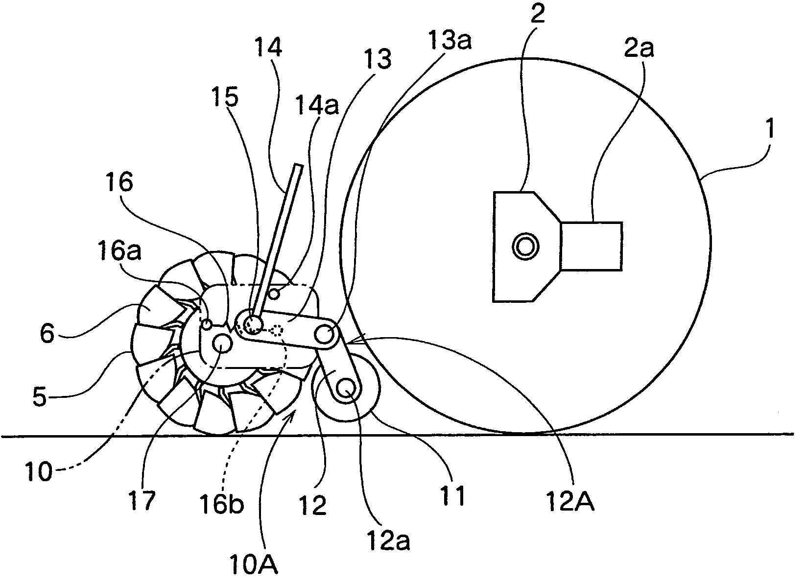
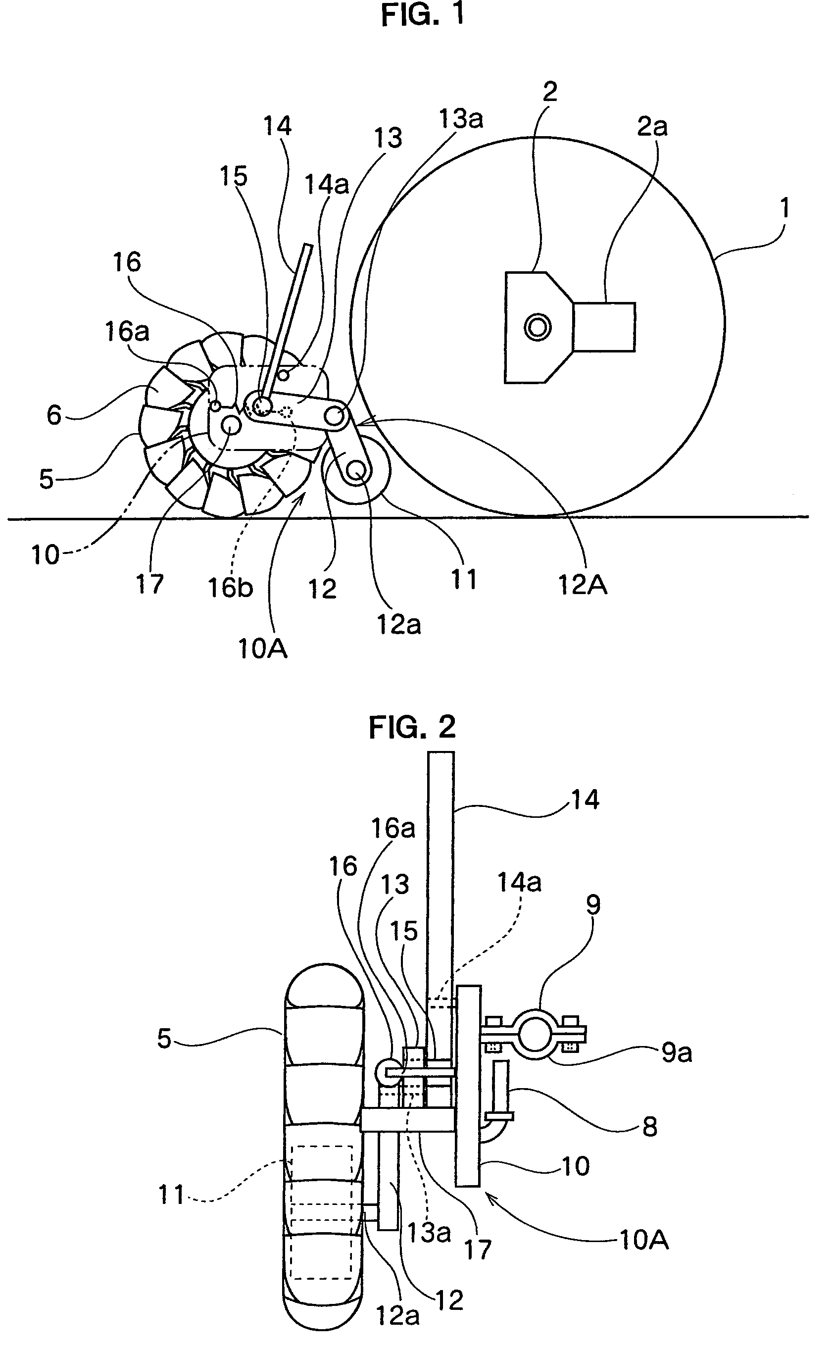
[0024]A motorized wheelchair according to an embodiment of the present invention will be described with reference to FIGS. 1 to 6. As shown in FIG. 6, the motorized wheelchair has right and left rear wheels 1 each to be driven by a corresponding drive unit 2 using a motor 2a provided on a body frame 7, front wheels 5 of a nonturning type, namely, fixed in a direction orthogonal to a rotational direction thereof, having a plurality of rollers 6 rotatable in a direction orthogonal to an alignment direction of the wheels are disposed for direction change around the wheels, and the wheelchair is differentially steered due by supplying a difference in the rotational speed between the right and left drive units 2.

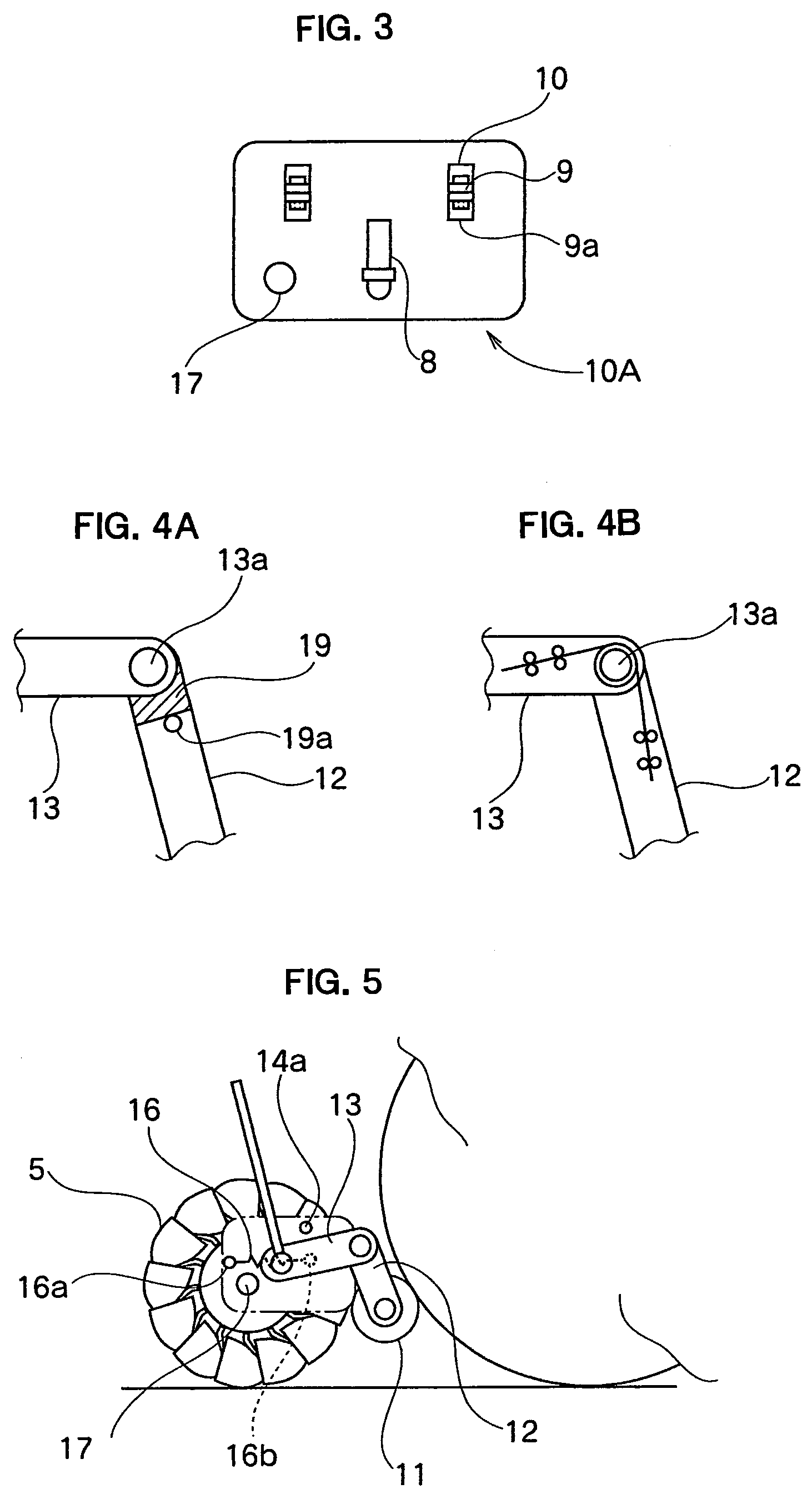
[0025]As shown in FIG. 2 and FIG. 3, the front wheels 5 are mounted on the right and left sides at positions with the treads of the front and rear wheels 1 and 5 being identical each other and a front wheel drive unit 10A having an axle 17 rotatably supporting the front wheels 5 ...


PUM


Abstract

A motorized wheelchair having transmission rollers to transmit the rotation of rear wheels to front wheels while being disposed at a transmission position between circumferential surfaces of front and rear wheels, a roller supporting arm for rotatably and oscillatingly supporting the transmission rollers in the front-rear direction of the wheelchair, and transmission roller pressure-contact springs for urging the roller supporting arm in a direction of the transmission position. An operation lever constrains the roller supporting arm in an interlocking manner in the direction away from the transmission position when being at the regular position, and releases the constrains when the operation lever being at the working position so as to allow the transmission rollers to be disposed at the transmission position.

Description

BACKGROUND OF THE INVENTION[0001]1. Field of the Invention[0002]The present invention relates to a motorized wheelchair having right and left motorized type rear wheels, and nonturning-type omni-directional front wheels having a plurality of rollers rotatable in a direction orthogonal to an alignment direction of the wheels are disposed for direction change around the wheels.[0003]2. Description of the Related Art[0004]As disclosed in Japanese Unexamined Patent Application Publication No. 8-56991 or Japanese Unexamined Patent Application Publication No. 10-179651, a two-wheel-drive motorized wheelchair is known, in which the wheels are rotatable with a circumferential surface of each wheel in a pressure contact state by drive rollers by attachably / detachably mounting a motor-driven drive unit for the auxiliary drive on the rear wheels of the motorized wheelchair. Further, as disclosed in Japanese Unexamined Patent Application Publication No. 2004-344289, a four-wheel-drive motorized...

Claims


Application Information

Patent Timeline
Patent Type & Authority Patents(United States)
IPC IPC(8): B62D11/02A61G5/04F16H37/12
CPCA61G5/045A61G5/046A61G5/06A61G5/10B60B19/003B60Y2200/84A61G2203/14B60B2310/305A61G2005/1054Y10S180/907A61G5/1054
Inventor TORITA, HIDEKI
Owner KANTO AUTO WORKS
Why Eureka
Try Eureka