
Eureka
For R&D, Eureka makes reading and utilizing patents & technical documents easy.
Eureka AIR
Designed for self-driven R&D workflows. Generate viable solutions, solve complex R&D challenges, empower your innovation with AI.

Eureka Materials
Designed for material experts only. Revolutionize your material R&D, from search, analyze, to developing new materials.

TechResearch
Generate reliable direction feasibility study reports for your R&D in just a few steps.

TechSeek
Discover and master advanced knowledge NOW. Basics, ideas, possibilities, all at once.

TechMind
As an expert in R&D Theories, TechMind can generates customized viable solutions instantly.

TechRisk
Analyze your overall solution with one click, know your potential R&D risks in advance.

TechMonitor
Get weekly tech updates, stay abreast of the latest tech innovations and key insights.
Sheet conveying apparatus and image forming apparatus
- Summary
- Abstract
- Description
- Claims
- Application Information
AI Technical Summary
Benefits of technology
Problems solved by technology
Method used
Image

Examples
first embodiment
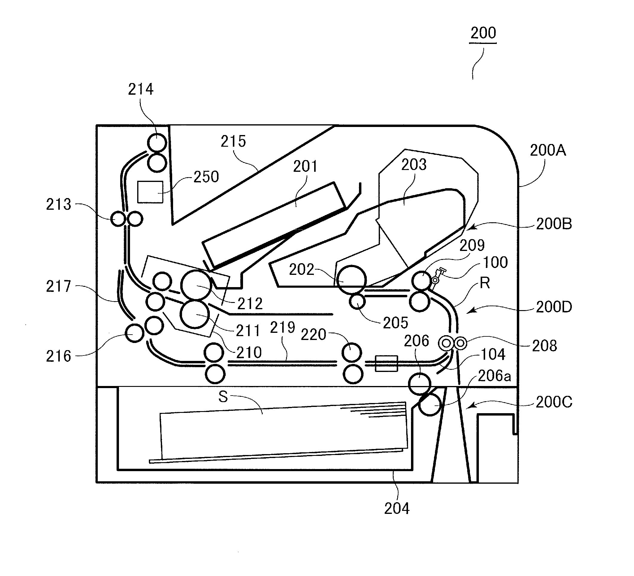
[0041]Modes for implementing the present invention will be described with reference to the drawings. FIG. 1 is a diagram illustrating a schematic configuration of a laser printer as one example of an image forming apparatus provided with a sheet conveying apparatus of the present invention. In FIG. 1, the laser printer includes, a laser printer body (referred to as an ‘apparatus body’ hereinafter) 200A and an image forming portion 200B provided in the apparatus body 200A. The laser printer 200 further includes a sheet feeding apparatus 200C provided in a lower part of the apparatus body 200A and a sheet conveying apparatus 200D conveying a sheet fed from the sheet feeding apparatus 200C to the image forming portion 200B.
[0042]The image forming portion 200B includes a cartridge unit 203 having a photoconductive drum 202, i.e., an image carrier, and a laser scanner 201 configured to expose the photoconductive drum 202. In forming an image, the photoconductive drum 202 is exposed by th...
second embodiment
[0067]Next, the present invention will be described.
FIG. 4 is a diagram illustrating a configuration of the sheet conveying apparatus of the present embodiment. In FIG. 4, the same reference signs as those in FIG. 2 described above indicate the same or corresponding portions. In FIG. 4, straight first and second conveyance guides 107a and 107b are provided between the conveying roller pair 208 and the registration roller pair 209 so as to oppose to each other and compose the sheet conveyance path R.
[0068]It is noted that in the present embodiment, the direction of the nip line of the conveying roller pair 208 corresponds to a direction in which the conveyed sheet is brought into abutment with the first conveyance guide 107a. More specifically, the conveying roller pair 208 is arranged such that the nip line of the nip portion N1 of the conveying roller pair 208 inclines in a direction approaching from the second rotator 209b side to the first rotator 209a side as the nip line advanc...
third embodiment
[0080]Next, the present invention will be described. FIG. 7 is a diagram illustrating a configuration of the sheet conveying apparatus of the present embodiment. In FIG. 7, the same reference signs as those in FIG. 5 described above denote the same or corresponding portions.
[0081]In FIG. 7, first and second conveyance guides 107c and 107d are provided between the conveying roller pair 208 and the registration roller pair 209 so as to oppose to each other and compose the sheet conveyance path R. The first conveyance guide 107c has a straight shape, and the second conveyance guide 107d, which is an opposed guide portion provided so as to oppose the first conveyance guide 107c, has a curved shape bulging outward. That is, the second conveyance guide 107d is formed curvedly in a direction away from the first conveyance guide 107c.
[0082]It is noted that in the present embodiment, the nip line of the conveying roller pair 208 runs in a direction in parallel with the first conveyance guid...
PUM
 Abstract
Description
Claims
Application Information
 - R&D Engineer
- R&D Manager
- IP Professional
- Industry Leading Data Capabilities
- Powerful AI technology
- Patent DNA Extraction
Browse by: Latest US Patents, China's latest patents, Technical Efficacy Thesaurus, Application Domain, Technology Topic, Popular Technical Reports.
© 2024 PatSnap. All rights reserved.Legal|Privacy policy|Modern Slavery Act Transparency Statement|Sitemap|About US| Contact US: help@patsnap.com