
Monolithic three-axis magnetic field sensor

a magnetic field sensor and monolithic technology, applied in the field of monolithic three-axis magnetic field sensors, can solve the problems of not being able to detect perpendicular detecting magnetic flux parallel to the device plane, and mr sensors

Active Publication Date: 2015-10-08
MEMSIC
View PDF2 Cites 22 Cited by
  • Summary
  • Abstract
  • Description
  • Claims
  • Application Information

AI Technical Summary

Benefits of technology

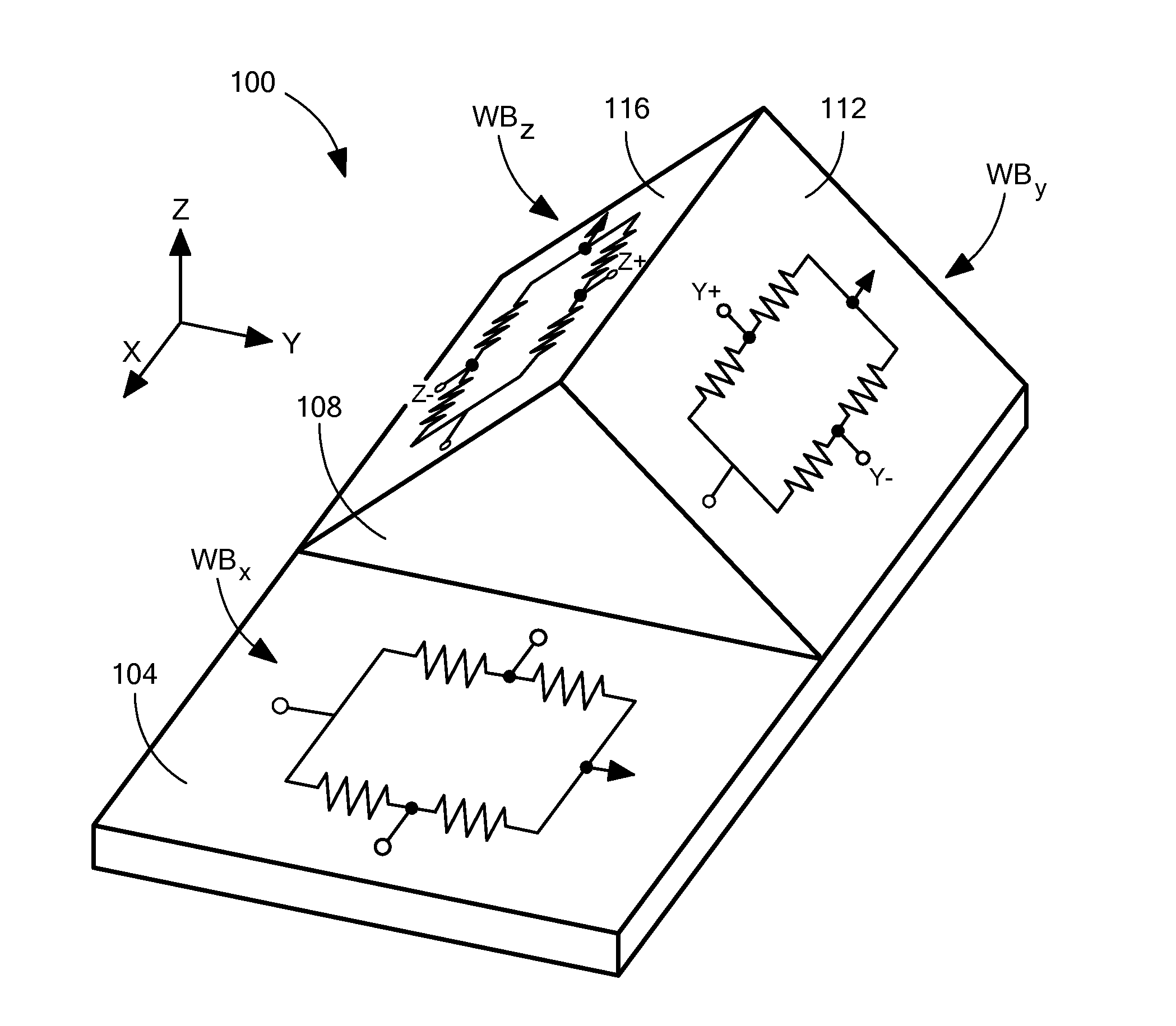
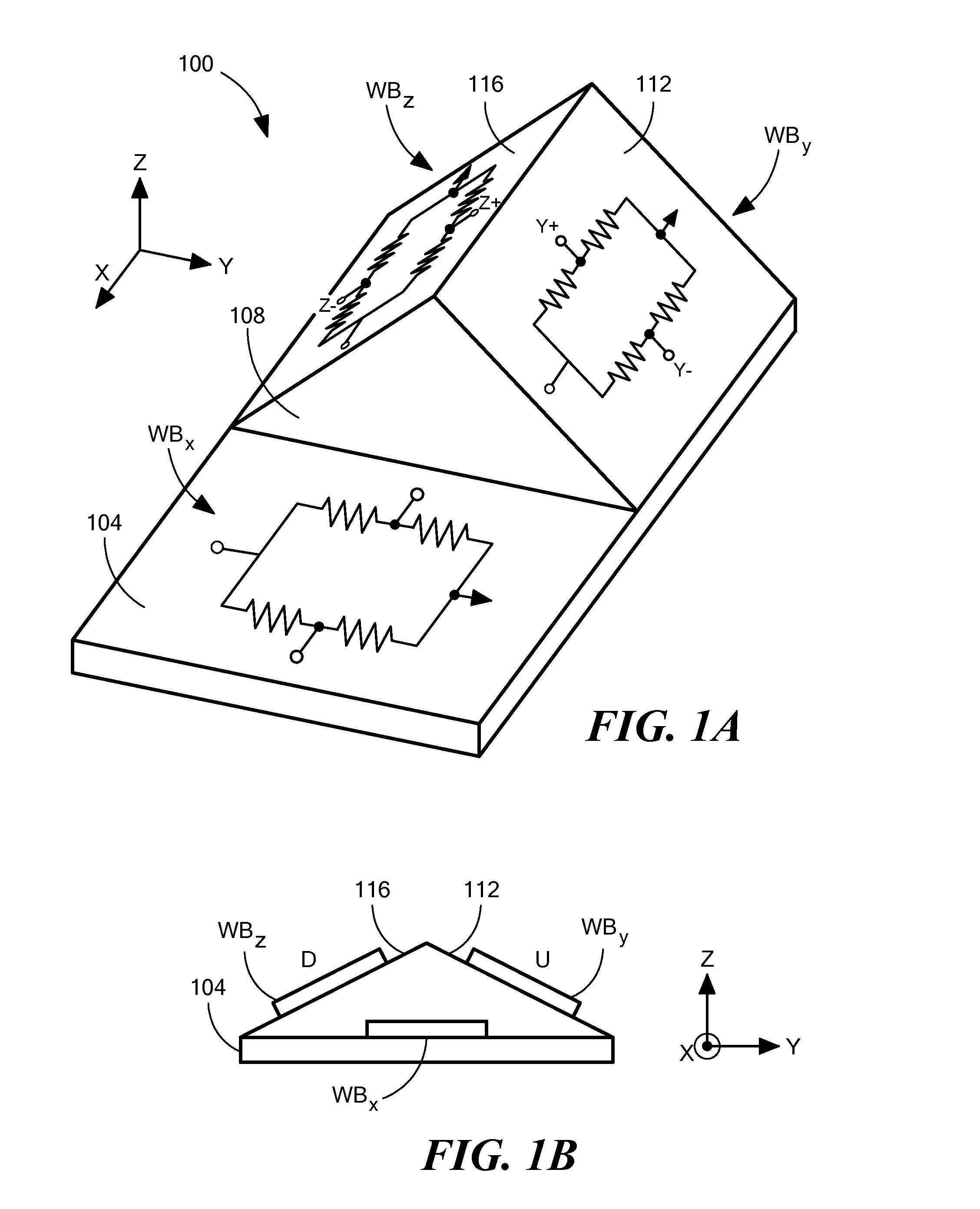
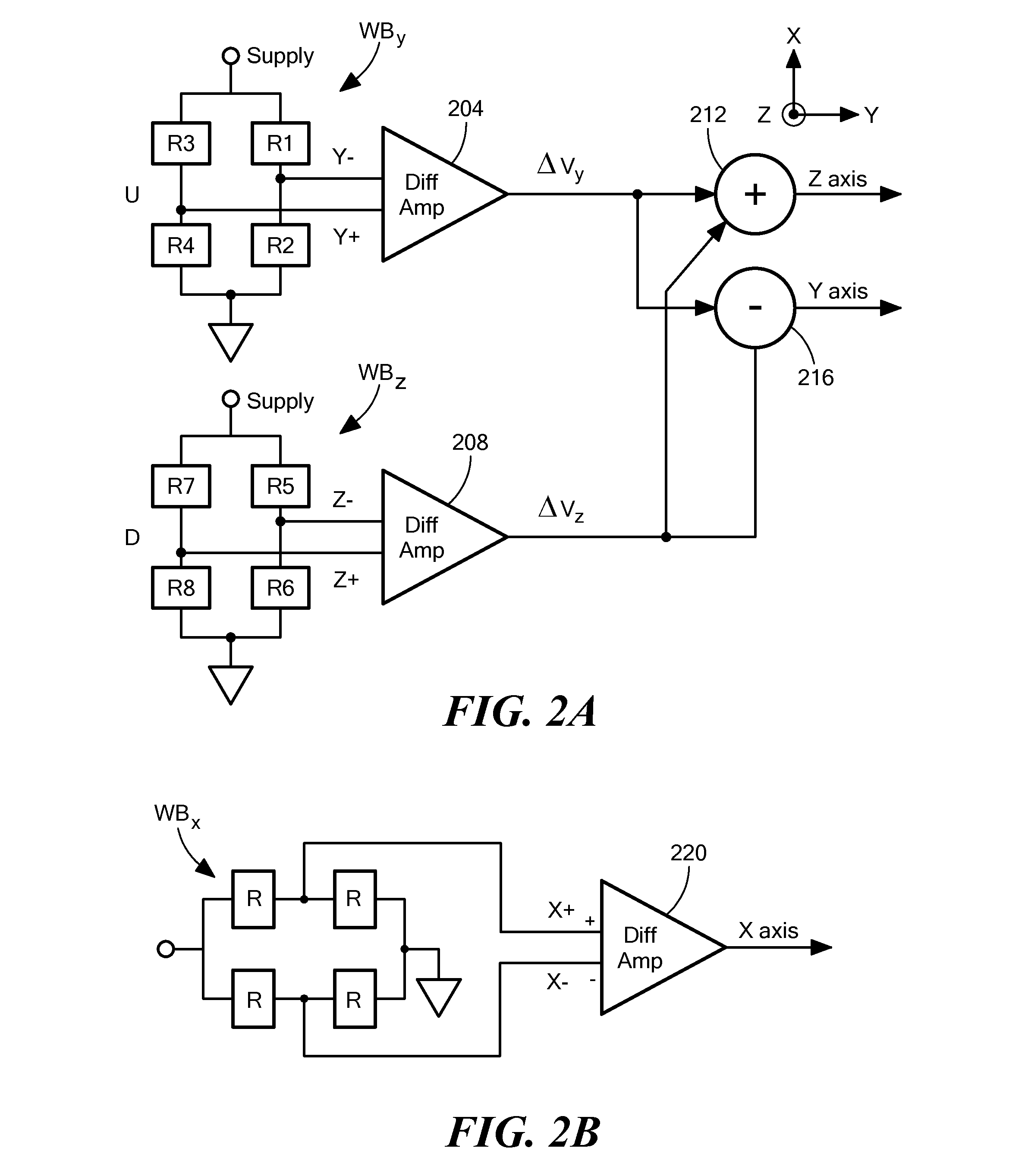
The patent text describes a three-axis magnetic sensor or magnetometer that has been fabricated using barber pole AMR structures on a silicon substrate. The sensor has a bump structure that is angled with respect to the flat surface of the substrate. The sensor can be oriented along the Y or X axis to produce Y and Z channel signals, or along both the Y and X axes to produce both Y and Z channel signals. The technical effect of this invention is the ability to measure magnetic fields in three directions simultaneously, providing more accurate and reliable results.

Problems solved by technology

Known magneto-resistive (MR) sensors, such as AMR (anisotropic MR) sensors, GMR (giant MR) sensors, TGMR (tunneling GMR) sensors, and the like, however, can only detect magnetic flux that is parallel to the device plane and cannot detect flux that is perpendicular to the device plane.
Thus complex geometric arrangements of these sensors are required in order to measure all three axes in a single device.
This particular orthogonal axis sensor mounting, however, can be technically challenging, and significantly increases the cost of manufacturing, as well as results in an increase in the thickness of the final product.
The '330 patent, however, is limited by the accuracy with which the inclined walls of the trench can be made so that they are at the same inclined angle.
There are disadvantages associated with each of the known approaches.
The additional packaging steps add significant cost to the whole product manufacturing process.
Furthermore, variation in the positioning angle complicates signal processing since cross-talk signals from the XY plane are introduced if the Z axis magnetic field sensor in not perfectly vertical.

Method used


Image

  • Monolithic three-axis magnetic field sensor
  • Monolithic three-axis magnetic field sensor
  • Monolithic three-axis magnetic field sensor

Examples


Embodiment Construction

[0021]In the following detailed description, numerous specific details are set forth in order to provide a thorough understanding of the embodiments of the present invention. It will be understood by those of ordinary skill in the art that these embodiments of the present invention may be practiced without some of these specific details. In other instances, well-known methods, procedures, components and structures may not have been described in detail so as not to obscure the embodiments of the present invention.

[0022]Prior to explaining at least one embodiment of the present invention in detail, it is to be understood that the invention is not limited in its application to the details of construction and the arrangement of the components set forth in the following description or illustrated in the drawings. The invention is capable of other embodiments or of being practiced or carried out in is various ways. Also, it is to be understood that the phraseology and terminology employed...


PUM


Abstract

A three-axis magnetic sensor or magnetometer is provided. Two magnetic sensor Wheatstone bridges using barber pole AMR structures are fabricated on opposite sides of a bump structure formed on a substrate to provide surfaces that are at a pre-determined angle with respect to the flat surface of the substrate. The bridge assembly is oriented along the Y axis and the bridges are interconnected such that Y and Z channel signals can be produced by processing of the bridge signals. The X channel signals are provided by an X axis sensor provided on the level surface of the substrate.

Description

BACKGROUND OF THE INVENTION[0001]Multi-axis magnetic sensors or magnetometers, such as three-axis magnetic sensors, are particularly desirable for modern electronic compass applications. Known magneto-resistive (MR) sensors, such as AMR (anisotropic MR) sensors, GMR (giant MR) sensors, TGMR (tunneling GMR) sensors, and the like, however, can only detect magnetic flux that is parallel to the device plane and cannot detect flux that is perpendicular to the device plane. On the other hand, Hall-effect sensors can sense magnetic flux that is perpendicular to the device plane, i.e., along the Z axis, but cannot sense magnetic flux parallel to the device plane, i.e., in the XY plane. Thus complex geometric arrangements of these sensors are required in order to measure all three axes in a single device.[0002]One of the most common types of magnetic field sensor is the well-known magnetoresistive (MR) sensor where, generally, the resistivity of the sensor varies according to a local magneti...

Claims


Application Information

Patent Timeline
Patent Type & Authority Applications(United States)
IPC IPC(8): G01R33/02G01R33/09G01R33/00
CPCG01R33/0206G01R33/096G01R33/0005G01R33/00
Inventor CAI, YONGYAOJIANG, LEYUEZAVRACKY, PAULZHAO, YANGGU, SHUO
Owner MEMSIC
Learn More