Control device, display device, and display device control method
a display device and control device technology, applied in the direction of instruments, static indicating devices, etc., can solve the problems of power consumption of display devices, and achieve the effects of preventing flicker from being recognized, reducing electric power consumption, and being easy to recogniz
- Summary
- Abstract
- Description
- Claims
- Application Information
AI Technical Summary
Benefits of technology
Problems solved by technology
Method used
Image
Examples
embodiment 1
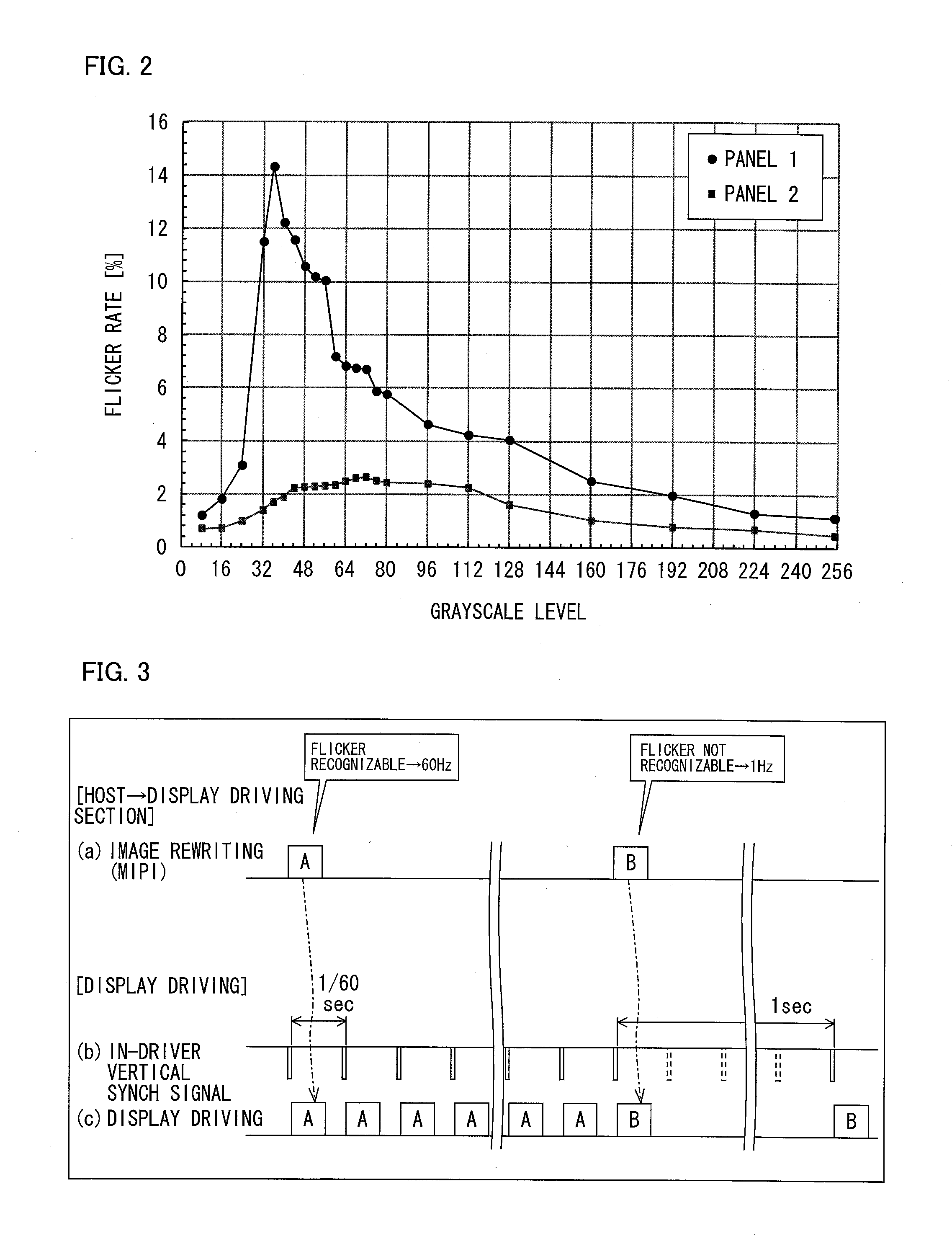
[0030]FIG. 2 is a graph showing flicker rates corresponding to respective grayscales levels at which an oxide semiconductor liquid crystal display panel is driven with a refresh rate of 1 Hz. A flicker rate indicates a degree to which flicker is recognizable, and a larger value of the flicker rate means greater recognizability of the flicker. A flicker rate of 1.5%, for example, is one indicator of whether or not flicker can be easily recognized. In a case where the oxide semiconductor liquid crystal display panel is driven at a low refresh rate, it is a grayscale level of an image that determines whether or not flicker easily occurs. In FIG. 2, a minimum grayscale level (black) is 0, whereas a maximum grayscale level (white) is 255. Note that recognizability of flicker also varies, depending on a screen size and production process. A panel 1 is a liquid crystal display panel greater in size than a panel 2. The panel 1 and the panel 2 also differ in production process.
[0031]A respon...
embodiment 2
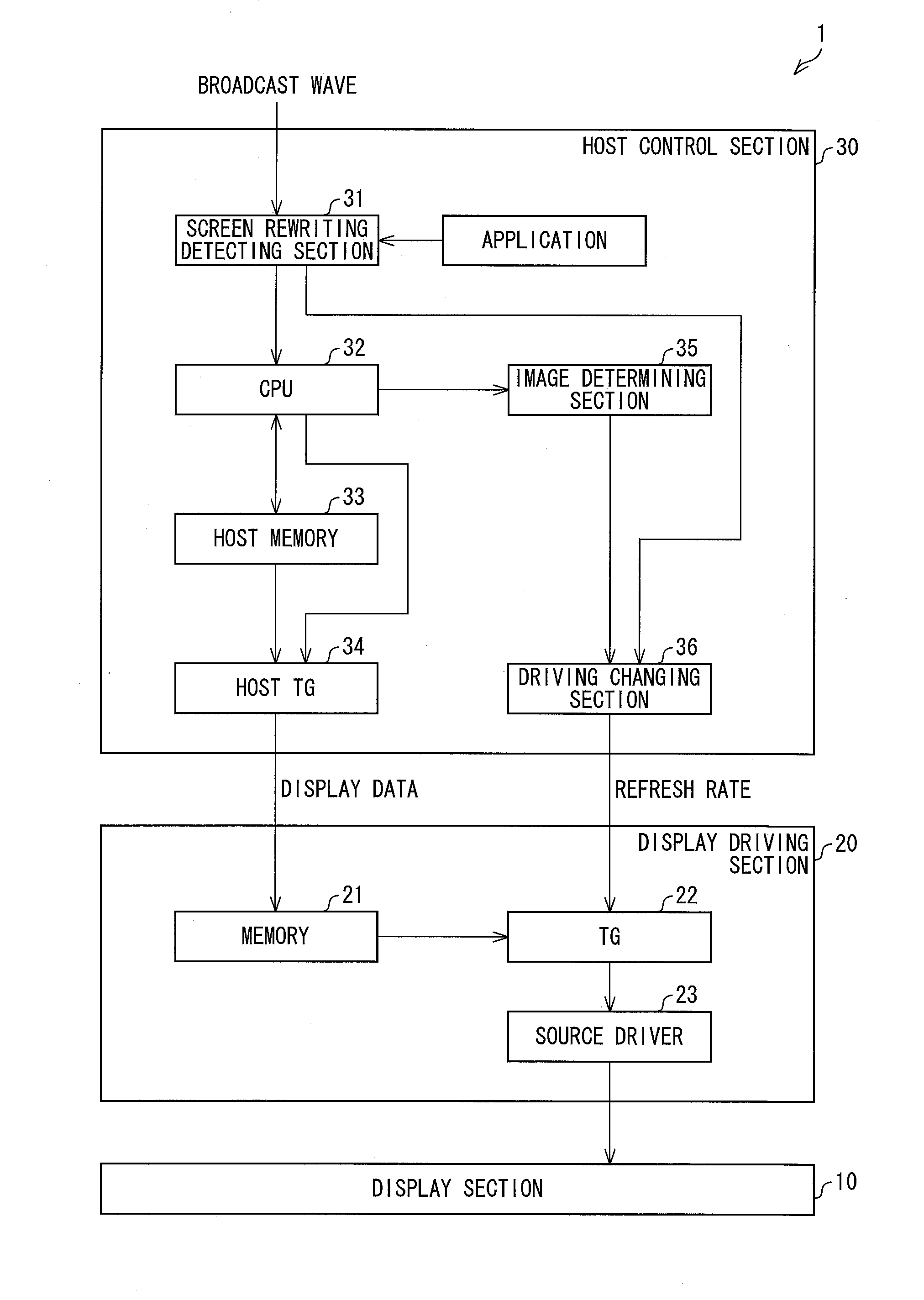
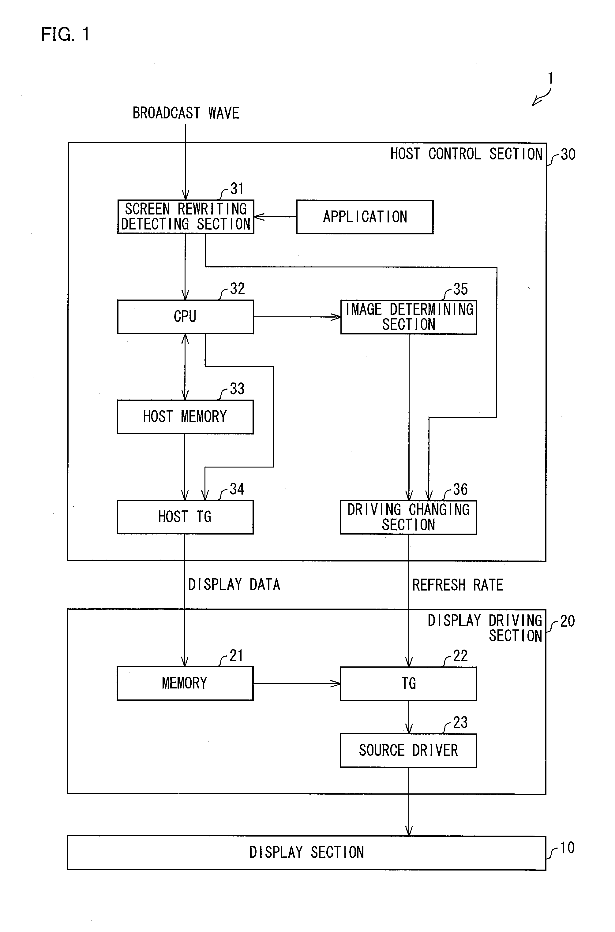
[0078]The following description will discuss another embodiment of the present invention. For convenience, members similar in function to those described in the foregoing embodiment will be given the same reference signs, and their description will be omitted. Embodiment 2 is similar to Embodiment 1 in terms of block configuration of a display device, but differs from Embodiment 1 in terms of a flow of a process of determining a refresh rate.
[0079](Flow 2 of Process of Determining Refresh Rate)
[0080]FIG. 6 is a view showing a flow chart of a process in which a host control section 30 of Embodiment 2 determines a refresh rate. The flow illustrated in FIG. 6 is carried out each time a screen rewriting detection section 31 detects rewriting of a displayed image (i.e. detects a change in content of the image).
[0081]When the screen rewriting detection section 31 detects, based on a display rewriting flag or the like, a change in content of an image, the screen rewriting detection section...
embodiment 3
[0102]The following description will discuss another embodiment of the present invention. For convenience, members similar in function to those described in the foregoing embodiment(s) will be given the same reference signs, and their description will be omitted. Embodiment 3 is similar to Embodiment 1 in terms of block configuration of a display device.
[0103](Image Determining Method 1)
[0104]In Embodiment 1, what is determined is the percentage of pixels, of all the pixels included in an image, which have grayscale levels falling within a predetermined range. Alternatively, it is possible to determine the percentage of pixels, of all pixels included in part of an image, which have grayscale levels falling within a predetermined range.
[0105](a) and (b) of FIG. 9 are views illustrating screens of respective display devices. Uniformity across capacitances of respective pixels depends on a production process. Therefore, a region of a screen of a display device, which region includes pi...
PUM
 Abstract
Description
Claims
Application Information
 - R&D
- Intellectual Property
- Life Sciences
- Materials
- Tech Scout
- Unparalleled Data Quality
- Higher Quality Content
- 60% Fewer Hallucinations
Browse by: Latest US Patents, China's latest patents, Technical Efficacy Thesaurus, Application Domain, Technology Topic, Popular Technical Reports.
© 2025 PatSnap. All rights reserved.Legal|Privacy policy|Modern Slavery Act Transparency Statement|Sitemap|About US| Contact US: help@patsnap.com


