
Decorative stone and metal bar for architectural use

a technology of decorative stone and metal rods, applied in the direction of wing knobs, handrails, film/foil adhesives, etc., can solve the problems of lack of tensile strength, stone has a tendency to crack, metal rods have no other purpose, etc., and achieve the effect of improving the overall attractiveness, usefulness and practicality of an installation

Active Publication Date: 2015-10-15
SCHWARTZ ROBERT
View PDF1 Cites 12 Cited by
  • Summary
  • Abstract
  • Description
  • Claims
  • Application Information

AI Technical Summary

Benefits of technology

The present invention is a way to reinforce and hold natural stone rods in a way that makes them more durable for use in architecture. This enhances the appearance, usefulness, and practicality of the installation, and allows for a wider range of applications. The attachment flanges or brackets at each end of the metal brace can be configured in different ways to meet different architectural requirements. One flange can be mounted horizontally to a vertical surface, while the other flange can be mounted on intersecting perpendicular walls to make a corner-mounted bar that maximizes space and stability. Overall, this invention makes it easier and more versatile to use natural stone rods in architecture.

Problems solved by technology

Large vertical columns have graced the facades of buildings since early Greco-Roman times. Natural stone is a durable and attractive building material but its use has been limited by its lack of tensile strength.
However, when a lateral force is applied that causes internal tension, for example when weight is applied to the center of a horizontal stone beam, the stone has a tendency to crack.
Once inserted, however, the metal rod fulfills no other purpose than to reinforce the stone bar.
This supporting fixture must presumably grip or clamp the outer surface of the stone which, being brittle, is subject to damage, either upon installation or during use.
Because this configuration as not robust, such stone bars may be considered impractical for architectural use.
It would be exceedingly difficult to drill a longitudinal hole through a stone rod from one end to the other.
The substantial cuts in the stone, for the purposed of reinforcement, result in a weakened stone structure which is naturally fragile and brittle and therefore subject to breakage.

Method used


Image

  • Decorative stone and metal bar for architectural use
  • Decorative stone and metal bar for architectural use
  • Decorative stone and metal bar for architectural use

Examples


Embodiment Construction

[0045]The preferred embodiments of the present invention will now be described with reference to FIGS. 1-22 of the drawings. Identical elements in the various figures are identified with the same reference numerals.

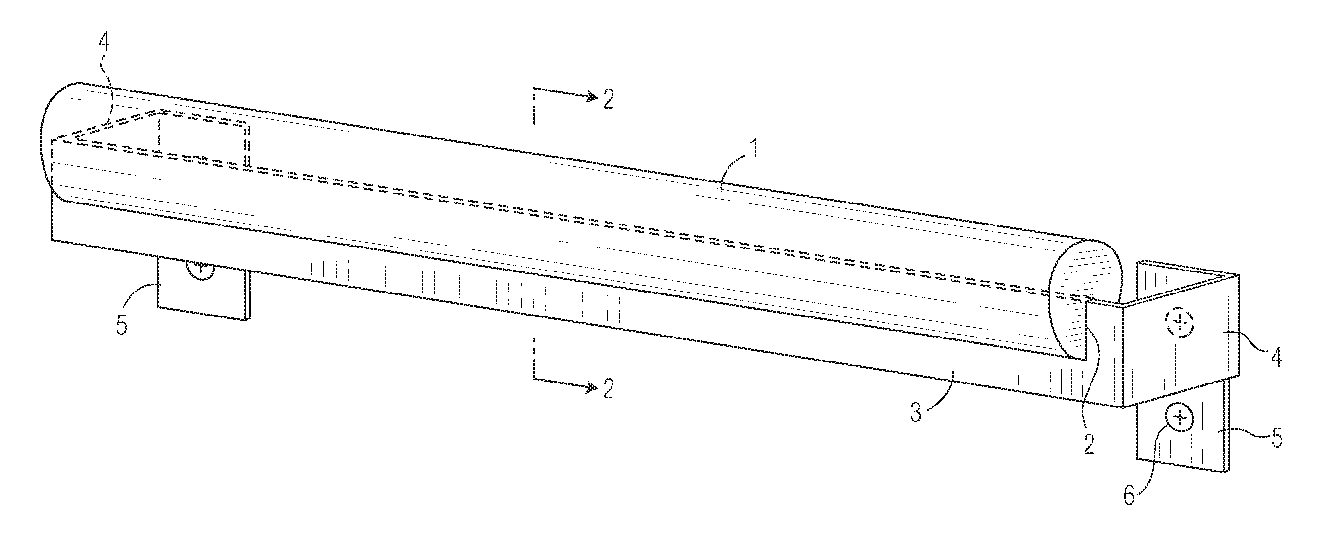
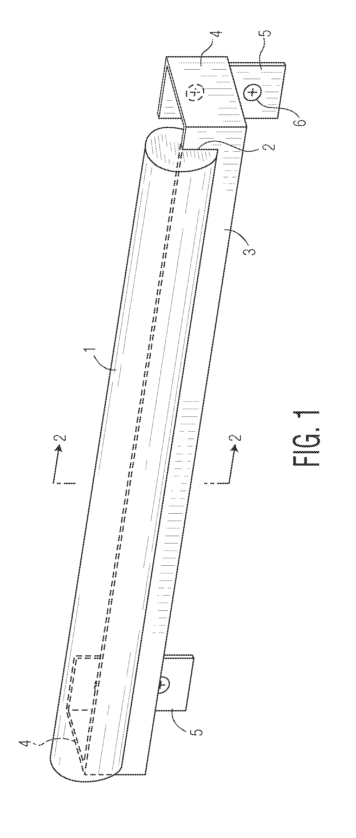
[0046]Briefly in overview, the present invention relates to a decorative rod formed of natural stone which is adhered to a metal armature or bracketed brace. The metal brace both reinforces the stone rod and provides a means for mounting the stone rod to a surface. The brace is configured to be mounted on a wall surface of a room or on a floor surface or post of a building, to provide an attractive and useful holder, such as a towel bar, hand rail or door pull.

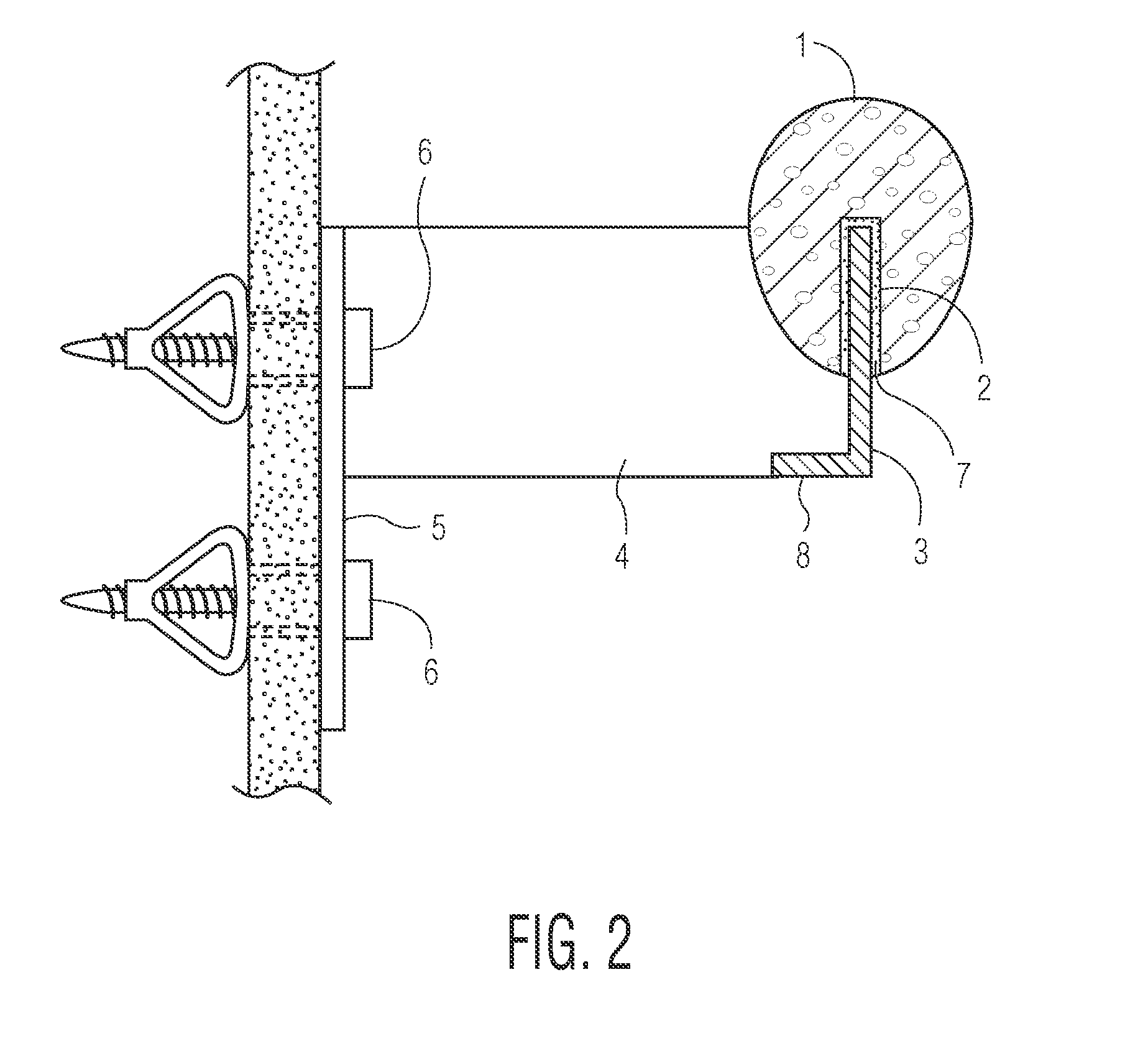
[0047]One preferred embodiment of this invention is the towel bar illustrated in FIGS. 1 through 5. FIG. 1 shows an elongate stone rod 1 that is egg-shaped in cross-section, supported on a metal armature. The metal armature is comprised of a front rail 3 with flanges 4 at both ends that turn 90 degrees towards the w...


PUM


Abstract

A decorative bar, configured to be mounted on a surface (wall or floor) of a room or building, comprises (a) an elongate rod formed of natural stone and having a substantially constant cross-sectional shape from a first end to an opposite, second end and a longitudinal groove extending along one side, and (b) an elongate metal armature or brace having a portion thereof inserted in and substantially filling the longitudinal groove in the stone rod. The metal brace has a flange or bracket at each end configured to be attached to the surface (wall or floor) of a building to affix and retain the stone rod in a mounted relationship to this surface with its longitudinal groove on a side which is not readily visible to a casual observer.

Description

CROSS-REFERENCE TO RELATED APPLICATION[0001]This application claims priority from Provisional Application No. 61 / 979,070 filed Apr. 14, 2014, and entitled “TOWEL BAR.”BACKGROUND OF THE INVENTION[0002]The present invention relates to a decorative bar or rail formed of a natural stone rod combined with a metal armature or bracketed structure which is configured to be mounted on a wall surface of a room or a floor surface of a building to provide an attractive and useful holder or railing.[0003]For example, the stone and metal bar may be installed on the wall of a bathroom for use as a towel holder or a hand support; it may be installed on a door as a door pull; it may be installed in a closet for use as a rod on which to hang clothes; or it may be mounted on vertical supports on the side of a staircase to serve as a hand or guard rail or as the cap on a railing at a balcony edge. In general, the present invention is intended to add an attractive architectural accent in any situation w...

Claims


Application Information

Patent Timeline
IPC IPC(8): B44C5/04
CPCB44C5/0415B44C5/0438A47K10/04A47K17/022E04F11/1804E04F11/1838E04F2011/1891E05B1/0015
Inventor SCHWARTZ, ROBERT
Owner SCHWARTZ ROBERT
Learn More