

Device, system and method for informing alarm
- Summary
- Abstract
- Description
- Claims
- Application Information
AI Technical Summary
Benefits of technology
Problems solved by technology
Method used
Image

Examples
Embodiment Construction
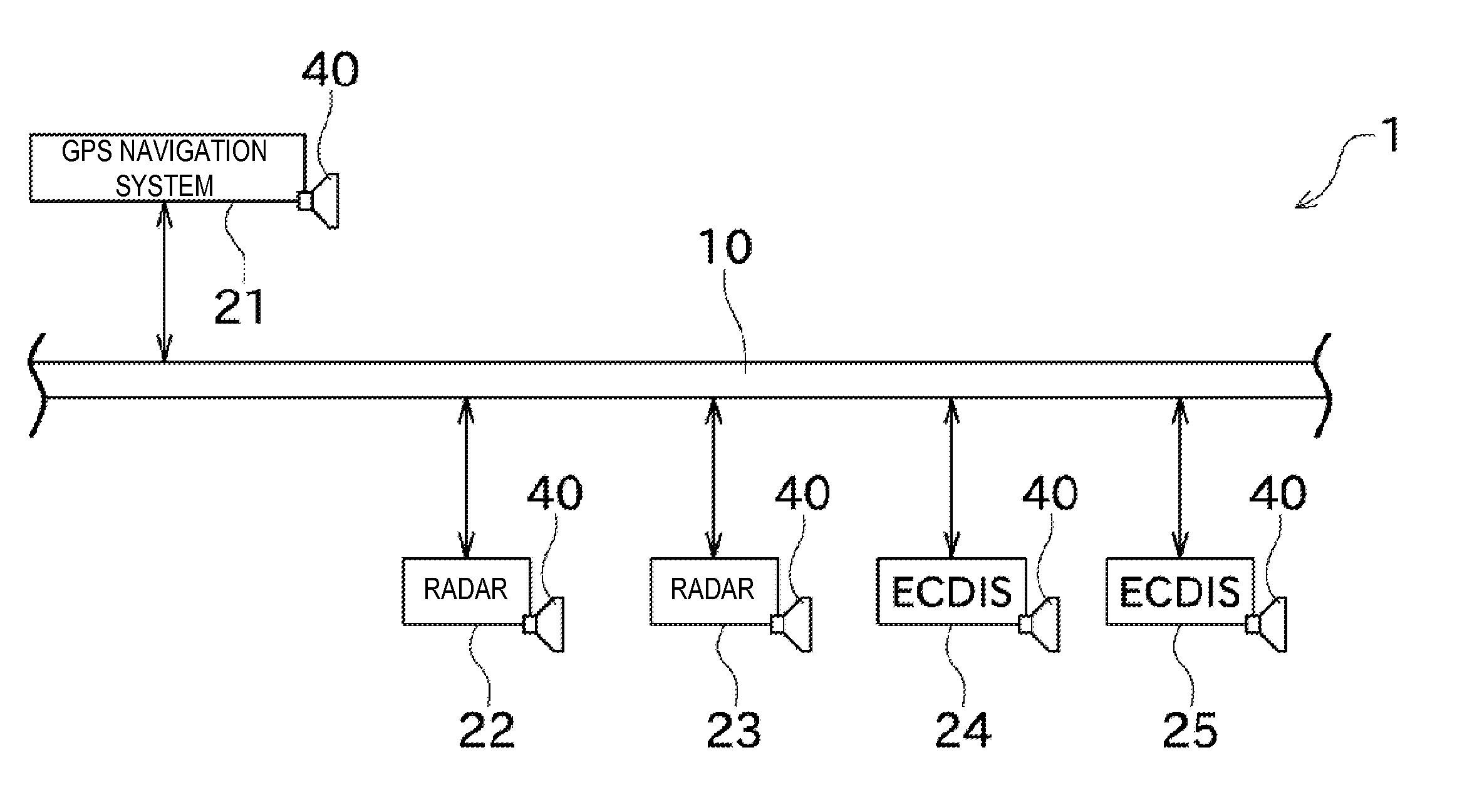
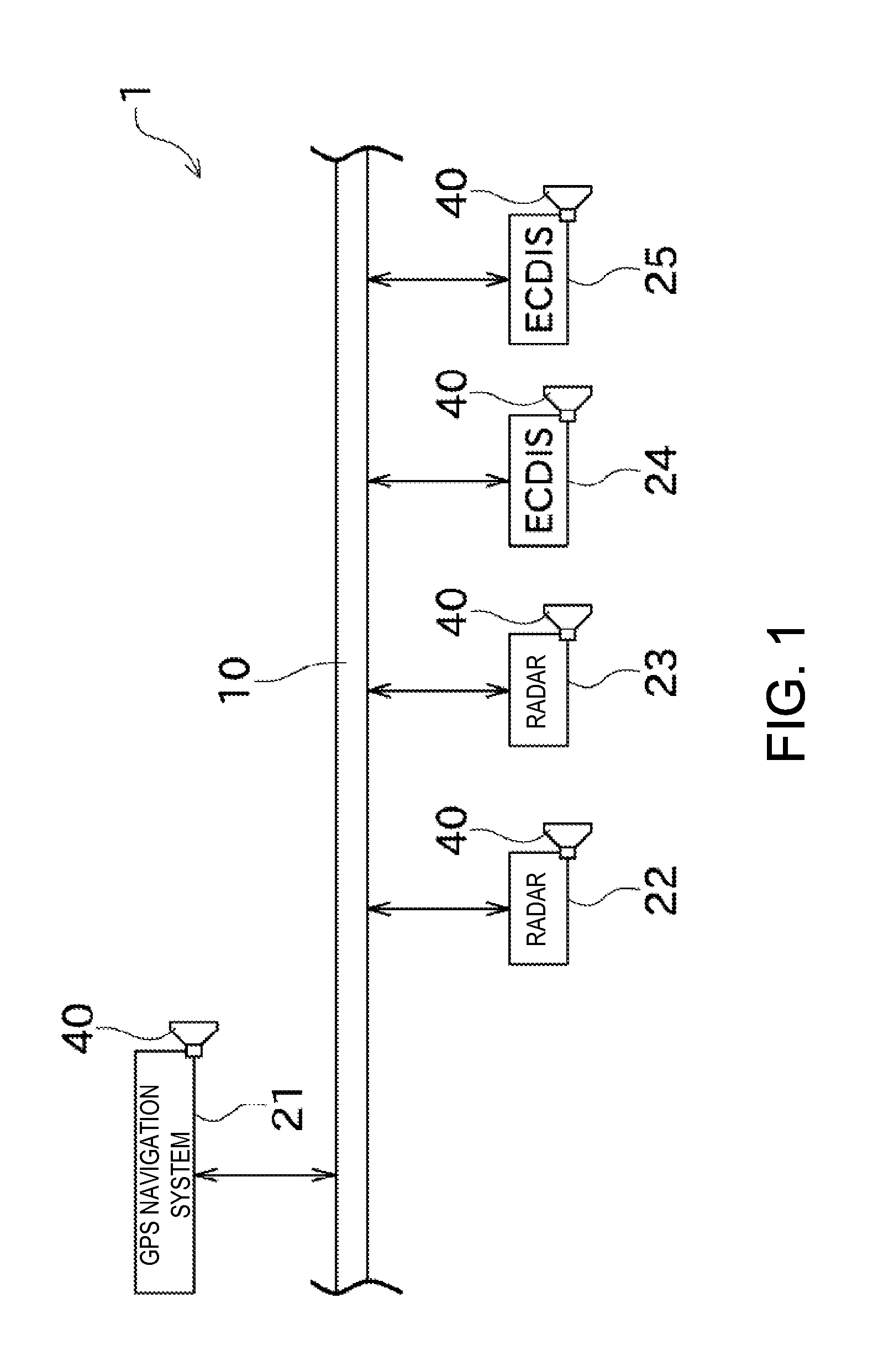
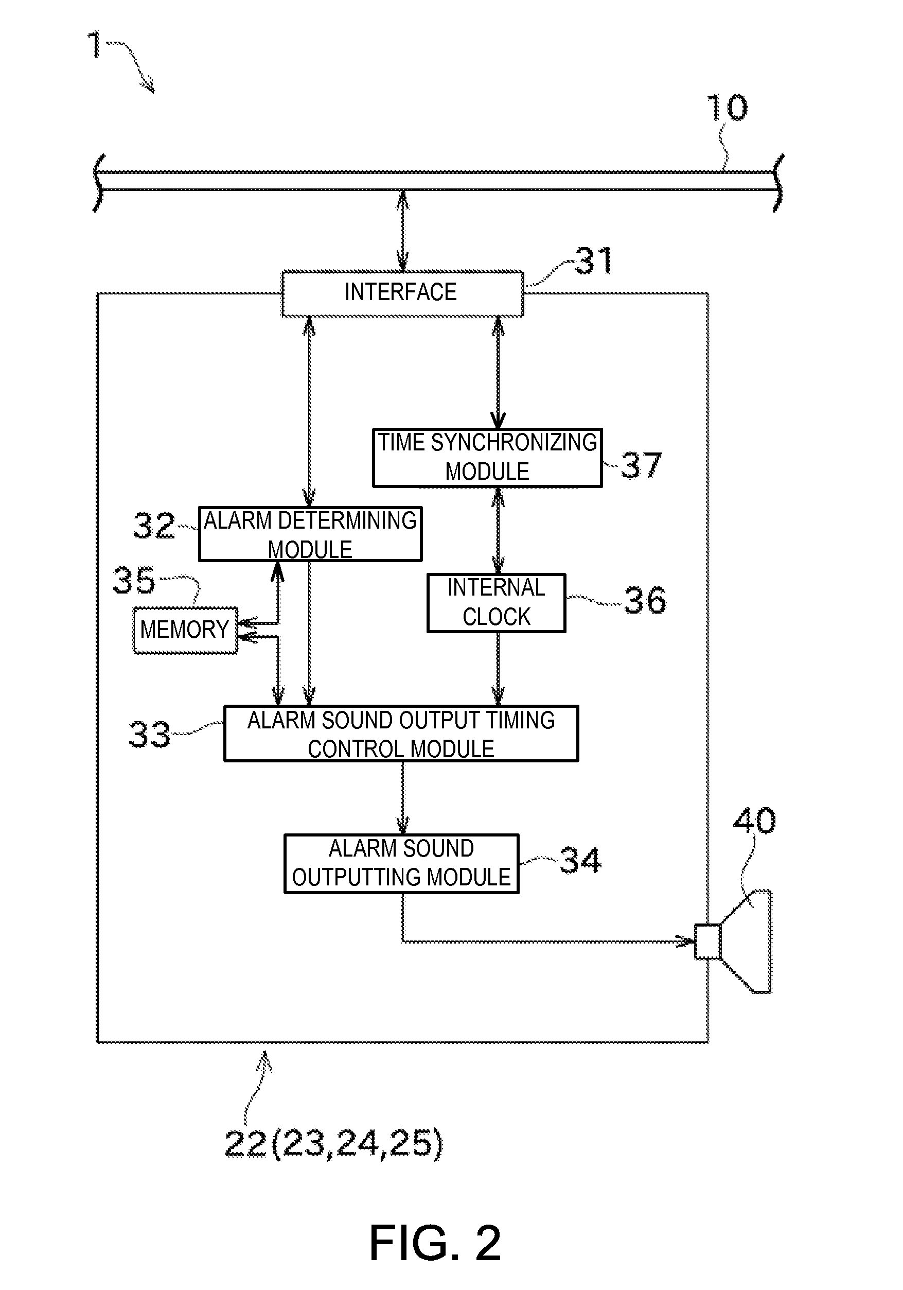
[0043]Next, embodiments of this disclosure are described with reference to the appended drawings. FIG. 1 is a schematic view of an alarm informing system 1 according a first embodiment of this disclosure. FIG. 2 is a block diagram illustrating a configuration for a control of an alarm sound outputted by a radar 22.
[0044]The alarm informing system 1 of the first embodiment provides navigation information to a user. The alarm informing system 1 includes a GPS navigation system 21, radars 22 and 23, and ECDISs 24 and 25. Note that, in the following description, components described above may simply be referred to as “instruments.” Among the instruments 21 to 25, each of the radars 22 and 23 and the ECDISs 24 and 25 informs an alarm to a user, and may be referred to as the alarm informing device.
[0045]These instruments 21 to 25 are installed in a bridge of a ship (movable body). Moreover, the instruments 21 to 25 are connected with a network 10 structured on the ship. The instruments 21...
PUM
 Abstract
Description
Claims
Application Information