Method and apparatus for transmitting synchronization signal for device to device communication in wireless communication system
a wireless communication system and synchronization signal technology, applied in the field of wireless communication, can solve the problems of significant deterioration of performance, difficulty in providing plan and controlled services of communication schemes using non-licensed bands, etc., and achieve the effect of efficient transmission, efficient indication and efficient synchronization
- Summary
- Abstract
- Description
- Claims
- Application Information
AI Technical Summary
Benefits of technology
Problems solved by technology
Method used
Image
Examples
embodiment 1-1
[0075]
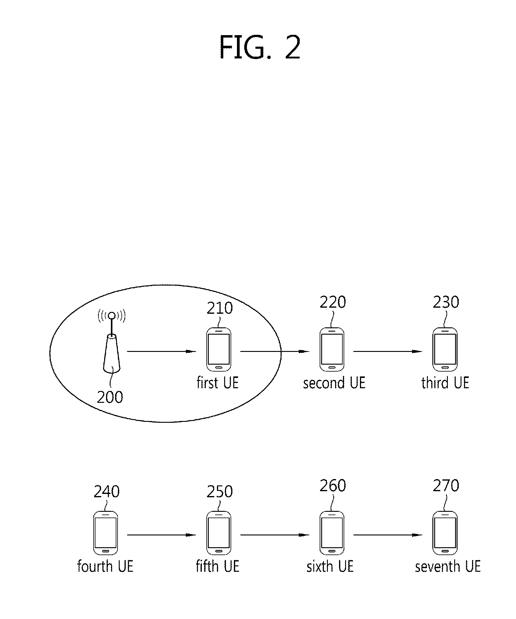
TABLE 5Type of SSStratum levelcaseTx SSoriginal SSPSSID(hop count)case 1:eNodeBPCID1steNodeB→UE1eNodeBeNodeBof eNodeB(Index 0 (or 1))case 2:SS relaying eNodeBPCID2ndeNodeB→UE1→UE2UE(=UE1)eNodeBof eNodeB(Index 1 (or 2))case 3:SS relaying eNodeBPCID3rdeNodeB→UE1→UE2→UE3UE(=UE2)eNodeBof eNodeB(Index 2 (or 3))case 4:ISSbased on1stISS(=UEA)→UEBUE(=UEA)ISS(=UEA)ISS(=UEA)(Index 0 (or 1))IDcase 5:SS relaying ISSbased on2ndISS(=UEA)→UEB→UECUE(=UEB)ISS(=UEA)ISS(=UEA)(Index 1 (or 2))IDcase 6:SS relaying ISSbased on3rdISS(=UEA)→UEB→UEC→UEDUE(=UEC)ISS(=UEA)ISS(=UEA)(Index 2 (or 3))ID
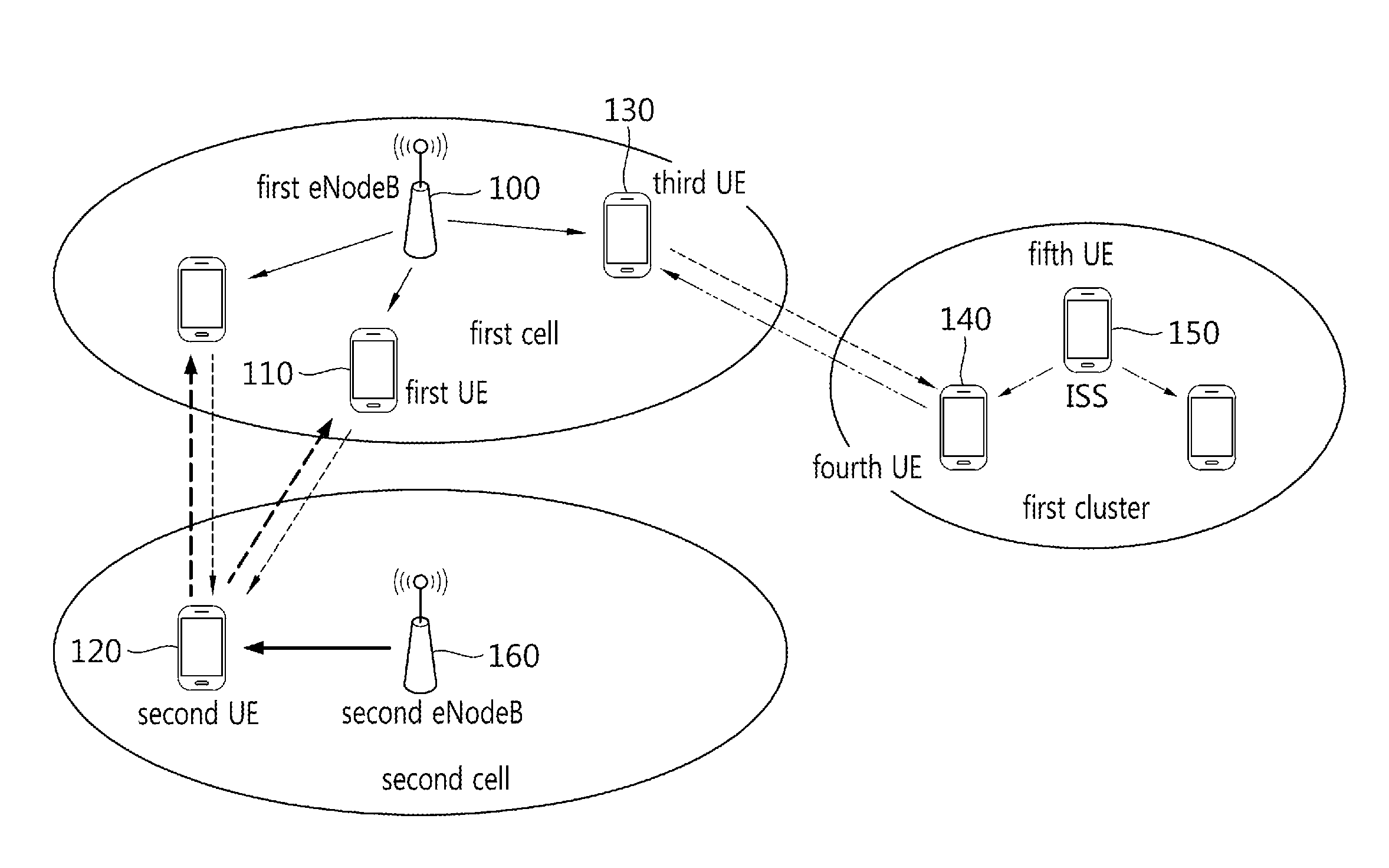
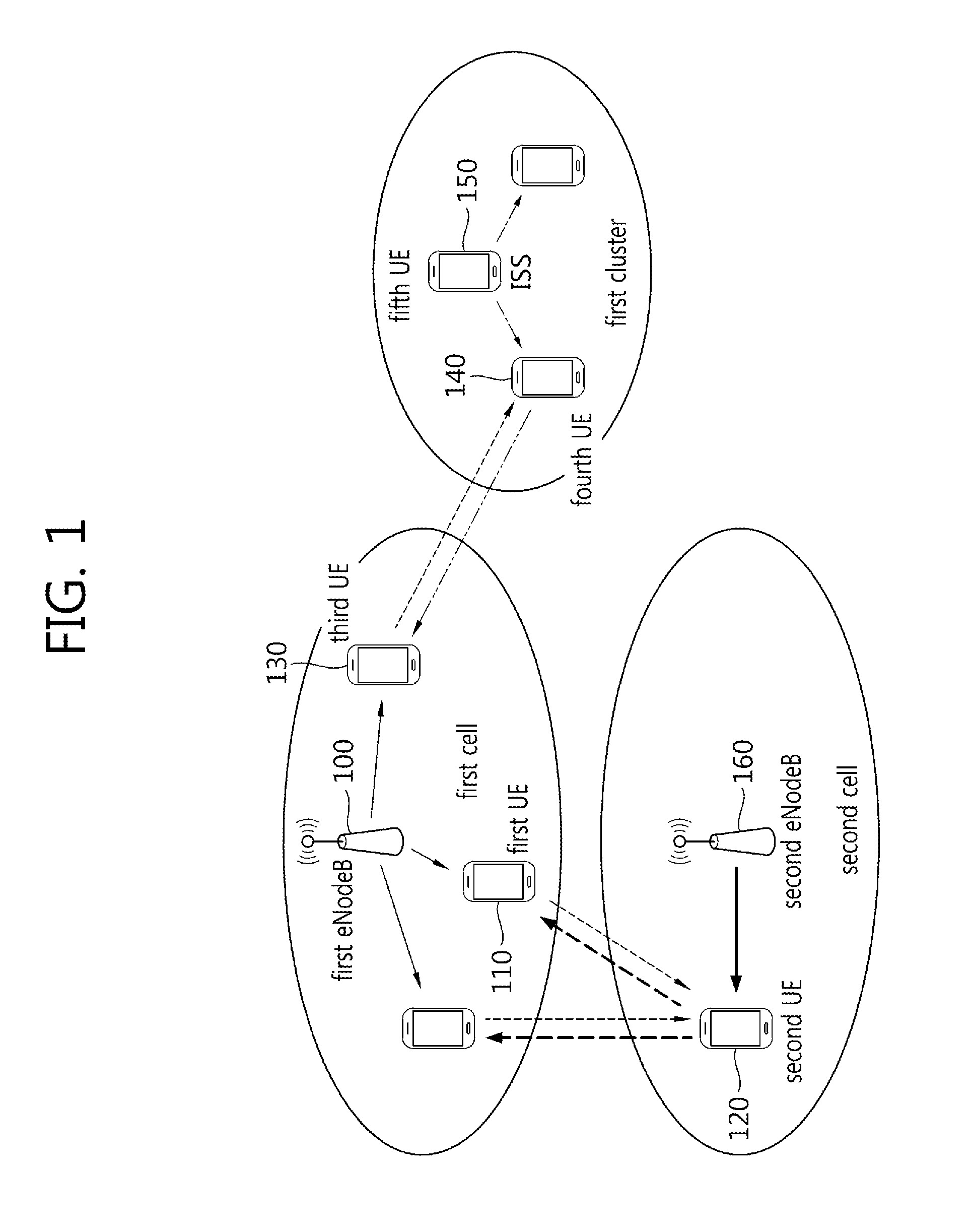
[0076]In the present embodiment, when a type of a Synchronization Source (SS) is an eNodeB or an SS derived from an eNodeB (an SS relaying an eNodeB), a PCID of an eNodeB may be used as a Physical Synchronization Source Identity (PSSID), and 504 unique PSSIDs may exist.
[0077]When a type of a Synchronization Source (SS) is an ISS or an SS derived from an ISS (an SS relaying an ISS), a PSSID based on a UE ID of t...
embodiment 1-2
[0084]
TABLE 6Type of SSStratum levelcaseTx SSOriginal SSPSSID(hop count)case 1:eNodeBPCID1steNodeB→UE1eNodeBeNodeBof eNodeB(Index 0 (or 1))case 2:SS relaying eNodeBbased on2ndeNodeB→UE1→UE2UE(=UE1)eNodeBPCID(Index 1 (or 2))of eNodeBcase 3:SS relaying eNodeBbased on3rdeNodeB→UE1→UE2→UE3UE(=UE2)eNodeBPCID(Index 2 (or 3))of eNodeBcase 4:ISSbased on1stISS(=UEA)→UEBUE(=UEA)ISS(=UEA)ISS(=UEA)(Index 0 (or 1))IDcase 5:SS relaying ISSbased on2ndISS(=UEA)→UEB→UECUE(=UEB)ISS(=UEA)ISS(=UEA)(Index 1 (or 2))IDcase 6:SS relaying ISSbased on3rdISS(=UEA)→UEB→UEC→UEDUE(=UEC)ISS(=UEA)ISS(=UEA)(Index 2 (or 3))ID
[0085]In the present embodiment, when the type of the Synchronization Source (SS) is an eNodeB, a PCID of the eNodeB may be used as a PSSID, and 504 unique PSSIDs may be used. When the type of the synchronization source is an SS derived from an eNodeB (an SS relaying an eNodeB), a value modified based on the PCID of the eNodeB may be used as a PSSID, and 168 or K unique PSSIDs may exist, wherein...
embodiment 1-3
[0092]
TABLE 7Type of SSStratum levelcaseTx SSOriginal SSPSSID(hop count)Case 1:eNodeBPCID1steNodeB→UE1eNodeBeNodeBof eNodeB(Index 0 (or 1))Case 2:SS relaying eNodeBPCID2ndeNodeB→UE1→UE2UE(=UE1)eNodeBof eNodeB(Index 1 (or 2))Case 3:SS relaying eNodeBPCID3rdeNodeB→UE1→UE2→UE3UE(=UE2)eNodeBof eNodeB(Index 2 (or 3))Case 4:ISSBased on1stISS(=UEA)→UEBUE(=UEA)ISS(=UEA)ISS(=UEA)(Index 0 (or 1))IDCase 5:SS relaying ISSBased on2ndISS(=UEA)→UEB→UECUE(=UEB)ISS(=UEA)ISS(=UEA)(Index 1 (or 2))IDCase 6:SS relaying ISSBased on3rdISS(=UEA)→UEB→UEC→UEDUE(=UEC)ISS(=UEA)ISS(=UEA)(Index 2 (or 3))ID
[0093]In the present embodiment, when a type of a Synchronization Source (SS) is an eNodeB or an SS derived from an eNodeB (an SS relaying an eNodeB), a PCID of an eNodeB may be used as a Physical Synchronization Source Identity (PSSID), and 504 unique PSSIDs may exist.
[0094]When the type of the Synchronization Source (SS) is an ISS or an SS derived from an ISS (an SS relaying an ISS), a PSSID based on a UE ID ...
PUM
 Abstract
Description
Claims
Application Information
 - R&D
- Intellectual Property
- Life Sciences
- Materials
- Tech Scout
- Unparalleled Data Quality
- Higher Quality Content
- 60% Fewer Hallucinations
Browse by: Latest US Patents, China's latest patents, Technical Efficacy Thesaurus, Application Domain, Technology Topic, Popular Technical Reports.
© 2025 PatSnap. All rights reserved.Legal|Privacy policy|Modern Slavery Act Transparency Statement|Sitemap|About US| Contact US: help@patsnap.com


