X-ray ct apparatus and tomography method

Active Publication Date: 2015-10-22
FUJIFILM HEALTHCARE CORP
View PDF25 Cites 27 Cited by
  • Summary
  • Abstract
  • Description
  • Claims
  • Application Information

AI Technical Summary

Benefits of technology

[0011]According to the present invention, it is possible to provide an X-ray CT apparatus with li

Problems solved by technology

That is, a tendency that the amount of image noise in the reconstructed image increases and the visibility of a lesion o

Method used


Image

  • X-ray ct apparatus and tomography method
  • X-ray ct apparatus and tomography method
  • X-ray ct apparatus and tomography method

Examples


first embodiment

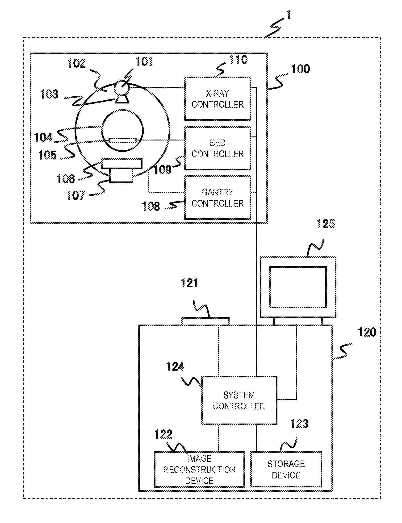
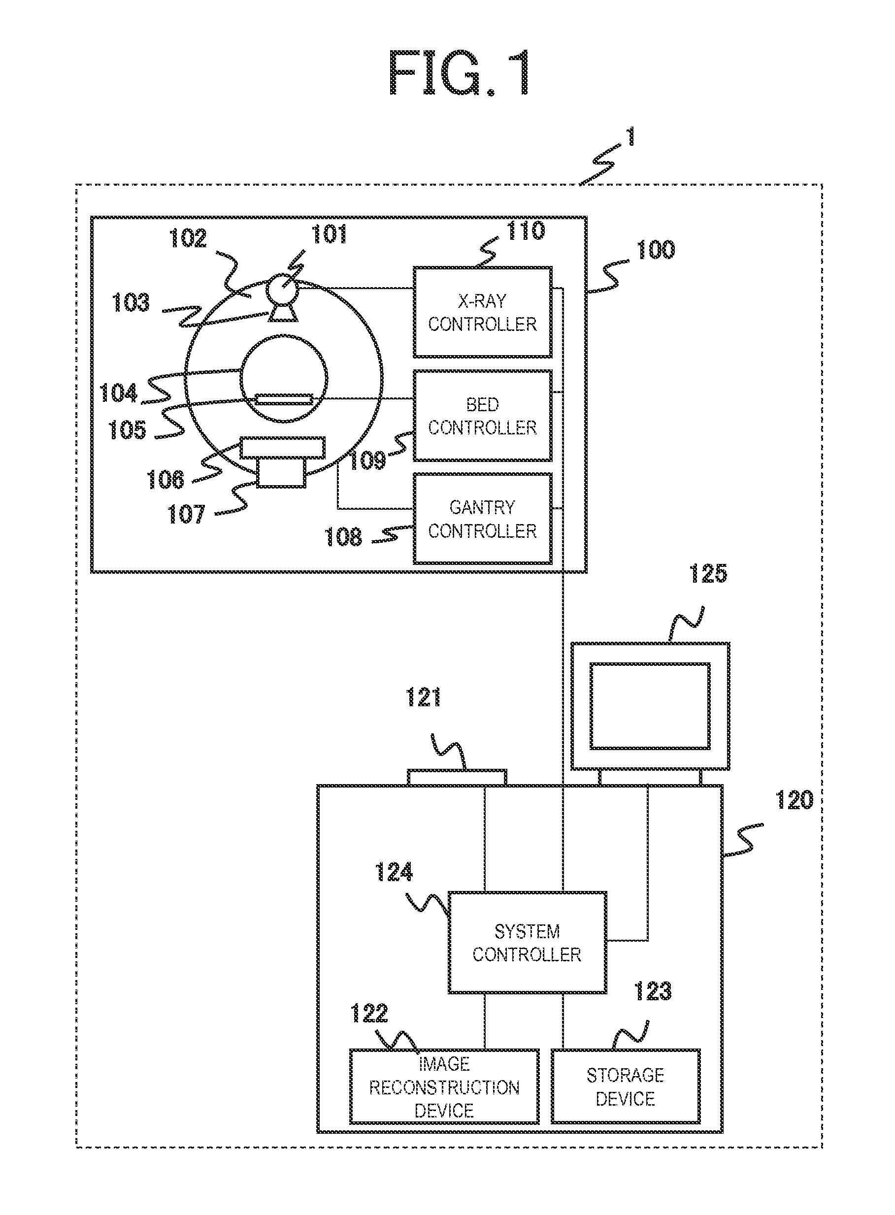
[0043]FIG. 1 is a diagram showing the overall configuration of an X-ray CT apparatus 1 that is an embodiment. The X-ray CT apparatus 1 includes a scan gantry unit 100 and a console 120.

[0044]The scan gantry unit 100 includes an X-ray tube 101, a rotary disk 102, a collimator 103, an X-ray detector 106, a data collection device 107, a bed 105, a gantry controller 108, a bed controller 109, and an X-ray controller 110. The X-ray tube 101 is a device for irradiating an object placed on the bed 105 with X-rays. The collimator 103 includes a mechanism for limiting the emission range of X-rays emitted from the X-ray tube 101 or an X-ray compensation filter for adjusting the dose distribution of X-rays. The rotary disk 102 includes an opening 104 through which the object placed on the bed 105 is inserted and also includes the X-ray tube 101, the X-ray detector 106, and the data collection device 107 mounted therein, and rotates around the object. The rotary disk 102 serves as a rotation me...

second embodiment

[0133]FIG. 17 is a diagram showing an operation according to a second embodiment of the present invention. Steps denoted by the same reference numerals as in FIG. 3 are approximately the same operations. Differences from the first embodiment shown in FIG. 3 are that a recommended condition is presented to the operator in step S311. As an example, conditions regarding the setting of the successive approximation process level and the setting of the image noise target value will be described as a recommended condition for the SD mode. A recommended condition for the CNR mode can also be similarly set. Hereinafter, step S311 will be described in detail. Since other steps are the same as in FIG. 3, explanation thereof will be omitted.

[0134]In step S307 of FIG. 17, it is determined from an input instruction or the like whether or not the current value of the X-ray tube 101 or the like displayed in the previous step S306 is an acceptable value. For example, when the predicted image noise v...

third embodiment

[0146]FIG. 21 is a diagram showing an operation according to a third embodiment of the present invention. Steps denoted by the same reference numerals as in the first embodiment shown in FIG. 3 indicate approximately the same operations. Differences from the first and second embodiments are that the successive approximation process level that can be selected in step S314 is limited in the present embodiment while any successive approximation process level is selected in step S304 in the first and second embodiments. In the second embodiment, a recommended condition is displayed in order to avoid clipping of the tube current, and these are displayed after the tube current value of the X-ray tube is calculated. In the present embodiment, however, the recommended condition is displayed when selecting the successive approximation process level before the tube current value of the X-ray tube is calculated. Hereinafter, it is assumed that N levels of Li (i=1, 2, . . . , N) are prepared as...


PUM


Abstract

In order to provide an X-ray CT apparatus with little image quality degradation even though a tube current value of the X-ray tube is suppressed, an X-ray CT apparatus of the present invention includes: a system controller that calculates a tube current value of an X-ray tube based on a successive approximation process condition selected from a plurality of successive approximation process conditions and input a scanning condition and/or a reconstruction condition and that performs scanning based on the calculated tube current value of the X-ray tube; and an image reconstruction device that reconstructs a tomographic image of an object, based on the selected successive approximation process condition and the reconstruction condition, from an amount of transmitted X-rays detected by an X-ray detector after being emitted from an X-ray source to the object based on the calculated tube current value of the X-ray tube and being transmitted through the object.

Description

TECHNICAL FIELD[0001]The present invention relates to an X-ray CT apparatus or an X-ray tomography method thereof.BACKGROUND ART[0002]An X-ray computed tomography (CT) apparatus is intended to reconstruct a tomographic image of an object using projection data from a plurality of angles that is obtained by rotating an X-ray source, which emits X-rays to an object, and an X-ray detector, which detects the amount of X-rays transmitted through the object as projection data, around the object, and display the reconstructed tomographic image. An image displayed in the X-ray CT apparatus is intended to depict, for example, the shape of an organ of the object, and is used for diagnostic scanning.[0003]As a general trend, in the X-ray CT apparatus, there is a trade-off between the exposure dose and the image quality. That is, a tendency that the amount of image noise in the reconstructed image increases and the visibility of a lesion or the like becomes worse when reducing the dose at the ti...

Claims


Application Information

Patent Timeline
IPC IPC(8): A61B6/00G06T7/00A61B6/03
CPCA61B6/5258A61B6/035A61B6/4435A61B6/54G06T2207/30004G06T7/0012G06T2207/10081G06T2207/10144A61B6/5205A61B6/032A61B6/405A61B6/488A61B6/5294A61B6/542A61B6/544A61B6/545H05G1/34H05G1/46
Inventor TANAKA, KANAHIROKAWA, KOICHIKUMAGAI, YUKIOYOSHIDA, RYO
Owner FUJIFILM HEALTHCARE CORP
Why Eureka
Try Eureka