
Image data processing device and method

a data processing device and image technology, applied in the field of image data processing apparatus, can solve the problems of inability to record image data on a fixed number of recording tracks, inability to easily splice mpeg-2 techniques, and low image quality, and achieve the effect of controlling the data occupancy and reducing the degradation of image quality

Inactive Publication Date: 2010-08-03
SONY CORP
View PDF14 Cites 3 Cited by
  • Summary
  • Abstract
  • Description
  • Claims
  • Application Information

AI Technical Summary

Benefits of technology

The present invention provides an improved and novel image data processing apparatus and method that overcomes the drawbacks of conventional image data processing apparatus and methods. Specifically, the invention provides a means for optimizing the data occupancy in a VBV buffer with little degradation of image quality, regardless of the initial value of the data occupancy. This is achieved by calculating the initial value of a bit occupancy in a VBV buffer based on auxiliary data read from a recording medium and controlling the number of bits for assignment to each GOP of image data accordingly. The invention provides an image data processor and method that can efficiently control the data occupancy in a VBV buffer, resulting in improved image quality and reduced data usage.

Problems solved by technology

However, with the MPEG-2 technique in which the intra-frame compression is used, it is not possible to record image data on a fixed number of recording tracks because the size of one frame varies.
Therefore, the MPEG-2 technique is not capable of easy splicing.
Generally, when the data occupancy is low for the size of the VBV buffer, the picture size will be limited for a picture whose amount of generated code data is large not to underflow the VBV buffer, and thus no sufficient amount of code can be assigned to a complicated image or I picture, which will result in a lower image quality.
On the other hand, if the data occupancy is high for the size of the VBV buffer, a stuffing will easily arise to prevent overflowing of the VBV buffer, the effective amount of generated code data is reduced correspondingly, which will also result in a lower image quality.
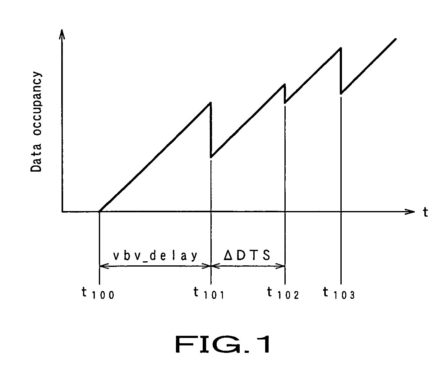
The initial value of the data occupancy in the VBV buffer, set based on a VBV delay (VBV_delay) acquired by reading auxiliary data in existent image data from a recording medium will no always be any optimum value and underflow or overflow will take place, which will continuously cause a lower image quality in many cases.

Method used


Image

  • Image data processing device and method
  • Image data processing device and method
  • Image data processing device and method

Examples


Embodiment Construction

[0044]The present invention will be described in detail below concerning the embodiments of the image data processing apparatus and method with reference to the accompanying drawings.

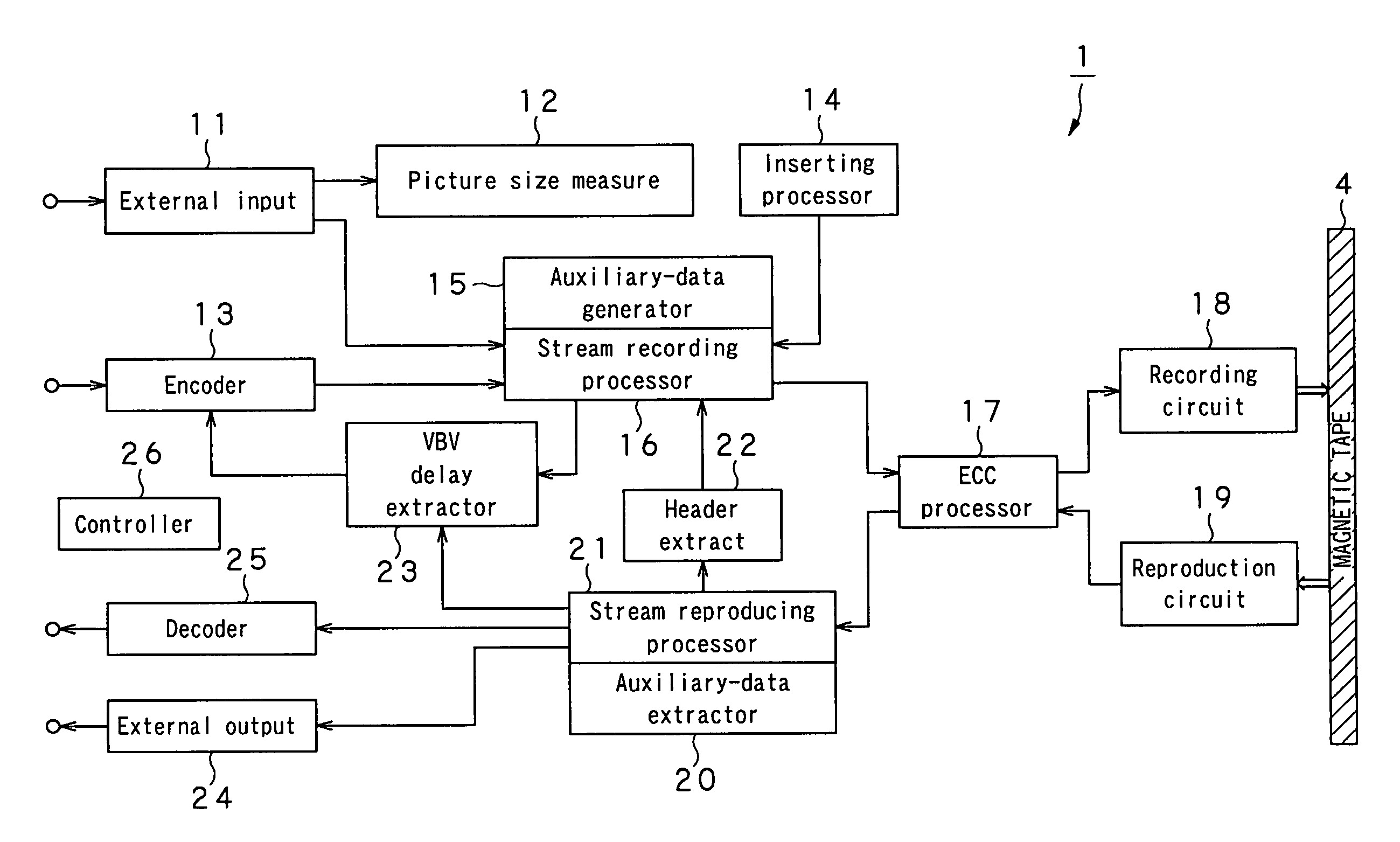
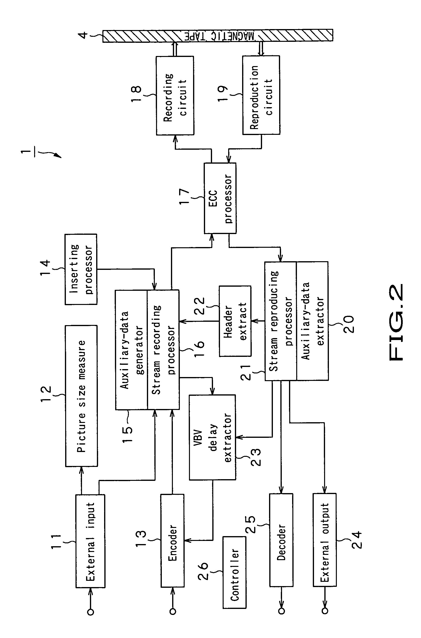
[0045]Referring now to FIG. 2, there is schematically illustrated in the form of a block diagram an image data processor for encoding a moving picture into a digital moving picture for recording to a magnetic tape with the MPEG-2 (ISO / IEC 13818) technique with which a moving picture is compressed efficiently by coding. As shown, the image data processor, generally indicated with a reference 1, includes an external input unit 11, picture size measurement unit 12, encoder 13, inserting processor 14, auxiliary-data generator 15, stream recording processor 16, ECC (error correction code) processor 17, recording circuit 18, reproduction circuit 19, auxiliary-data extraction unit 20, stream reproducing processor 21, header extraction unit 22, VBV (video buffering verifier) display extraction unit 23, external...


PUM


Abstract

The present invention provides an image data processing method of recording image data coded with the MPEG (Moving Picture Experts Group) technique to a recording medium. For transition of the bit occupancy in a VBV buffer to a target value, the initial value of a bit occupancy in a VBV buffer is calculated on the basis of auxiliary data read from a recording medium, a comparison is made between the target and initial values of the bit occupancy, and the number of bits for assignment to each GOP of to-be-coded image data correspondingly to the result of comparison.

Description

TECHNICAL FIELD[0001]The present invention relates to an image data processing apparatus for, and an image data processing method of, recording image data encoded with the MPEG (Moving Picture Expert Group) technique to a recording medium.[0002]This application claims the priority of the Japanese Patent Application No. 2002-199072 filed on Jul. 8, 2002, the entirety of which is incorporated by reference herein.BACKGROUND ART[0003]To compress a moving picture efficiently by coding, there have been proposed digital moving picture coding techniques represented by MPEG-2 (ISO / IEC 13818). In this image compression with the MPEG-2 technique, a hybrid conversion including a combination of inter-image motion compensation and DCT (discrete cosine transform) is effected to make further quantization and variable-length coding of a signal resulted from the conversion.[0004]The MPEG-2 technique adopts the bidirectional predictive coding technique to encode a moving picture. This bidirectional pr...

Claims


Application Information

Patent Timeline
Patent Type & Authority Patents(United States)
IPC IPC(8): H04N7/32H04N5/782H04N5/7826H04N5/92H04N9/804H04N19/115H04N19/134H04N19/152H04N19/177H04N19/196H04N19/44H04N19/50H04N19/70H04N19/85
CPCG11B20/00007H04N19/177H04N9/8042H04N21/433H04N19/46H04N19/115H04N19/61H04N19/152G11B20/10527G11B2020/00072G11B2020/10537G11B2020/10703G11B2020/10759G11B2020/10805G11B2020/10814H04N5/91
Inventor HIMENO, TAKUJIHASHIMOTO, YASUHIROTSUCHIDA, HIROYASUABE, FUMIYOSHIMIYAKOSHI, TOMOYUKI
Owner SONY CORP
Learn More