Dot arrangement determination method, program and apparatus, threshold matrix creating method and program, and image forming apparatus

a threshold matrix and determination method technology, applied in the field of dot arrangement determination methods, can solve the problems of reduced image quality and inability to determine the optimum dot arrangement based on visual characteristics, and achieve the effect of reducing non-uniformities

Inactive Publication Date: 2006-04-06
FUJIFILM CORP
View PDF7 Cites 15 Cited by
  • Summary
  • Abstract
  • Description
  • Claims
  • Application Information

AI Technical Summary

Benefits of technology

[0008] The present invention has been contrived in view of such circumstances, and an object thereof is to provide a method and apparatus for determining a dot arrangement that use a combination of an evaluation function and an optimization technique based on the visual characteristics and that have the effects of reducing nonuniformities resulting from dot gaps, and to provide a method for creating a threshold matrix; another object of the present invention is to provide an image forming apparatus in which a program for executing this method with a computer and the threshold matrix created by this method are used.

Problems solved by technology

For example, when a particular nozzle in a group of nozzles fails to eject, the dots that should have originally been deposited by the nozzle are missing, which results in unintended flaws in the form of lines (streaking) in the recorded image on the recording medium, and the image quality is reduced.
However, in the techniques proposed in the prior art, the technique of reducing nonuniformities (in the line patterns or concentration) resulting from omitted dots (so-called “dot gaps”) due to nozzle ejection failures or the like is not investigated in terms of visual characteristics, and the optimum dot arrangement based on visual characteristics is not determined.

Method used


Image

  • Dot arrangement determination method, program and apparatus, threshold matrix creating method and program, and image forming apparatus
  • Dot arrangement determination method, program and apparatus, threshold matrix creating method and program, and image forming apparatus
  • Dot arrangement determination method, program and apparatus, threshold matrix creating method and program, and image forming apparatus

Examples


Embodiment Construction

Description of Dot Arrangement Determination Method

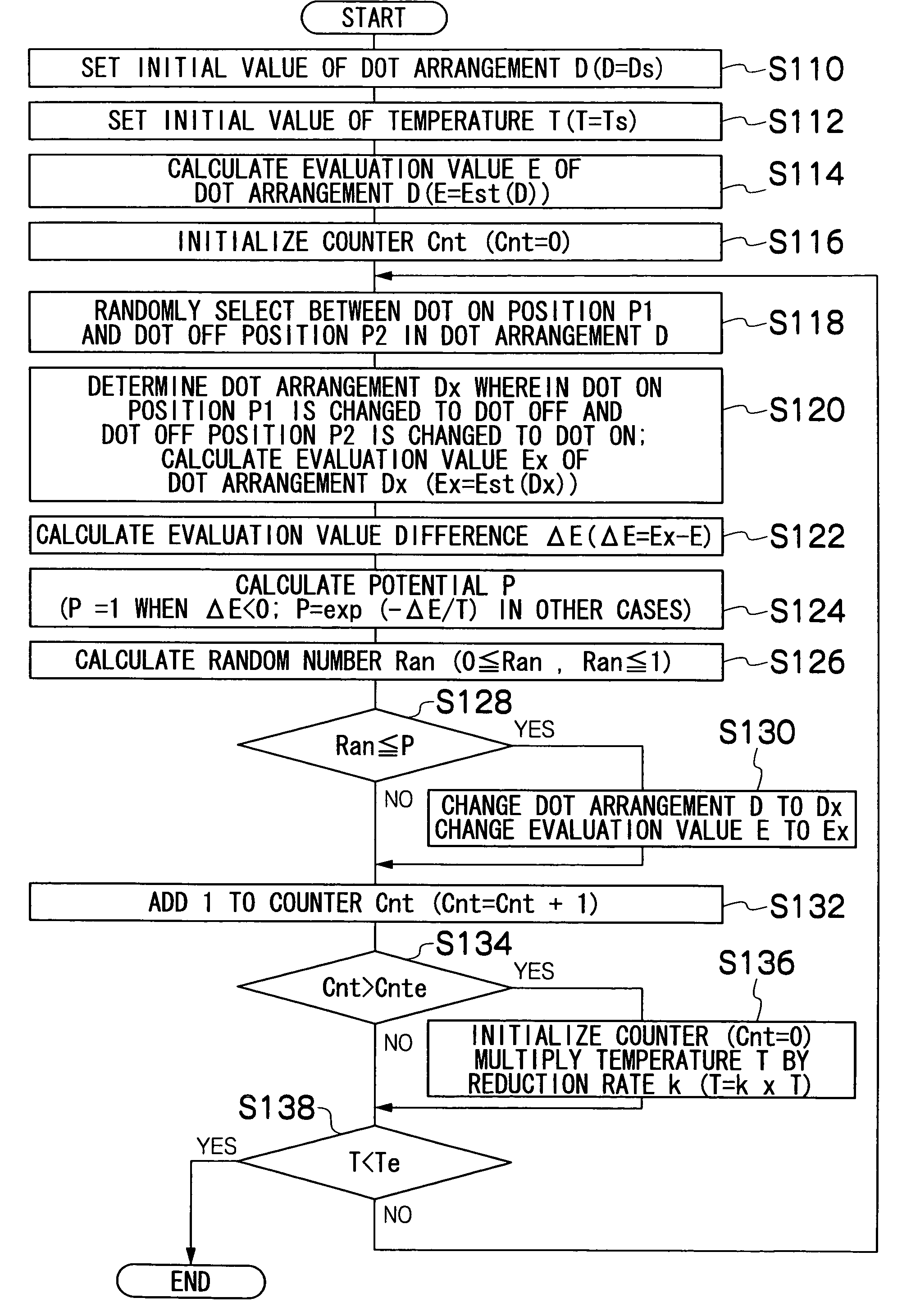
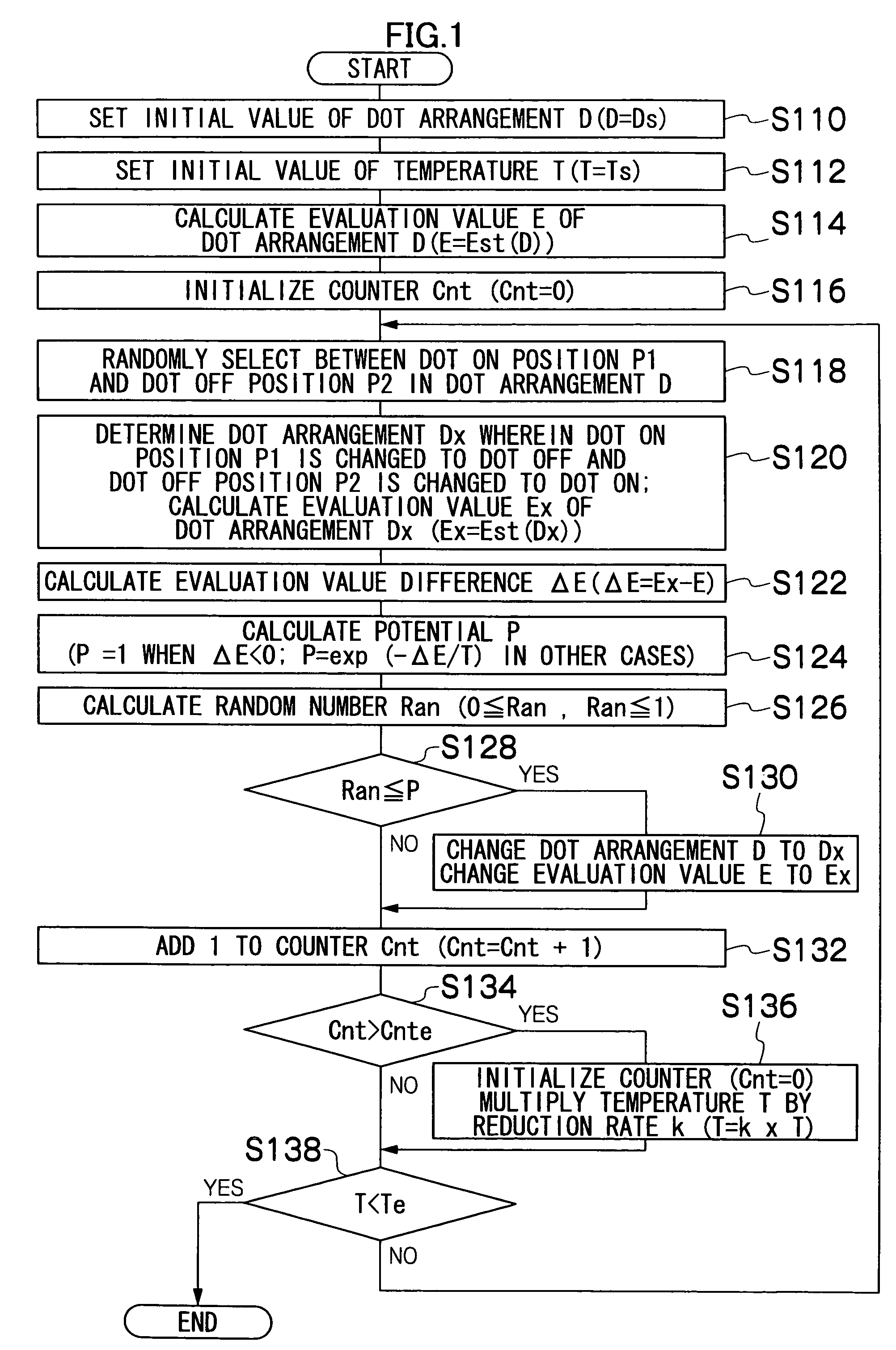
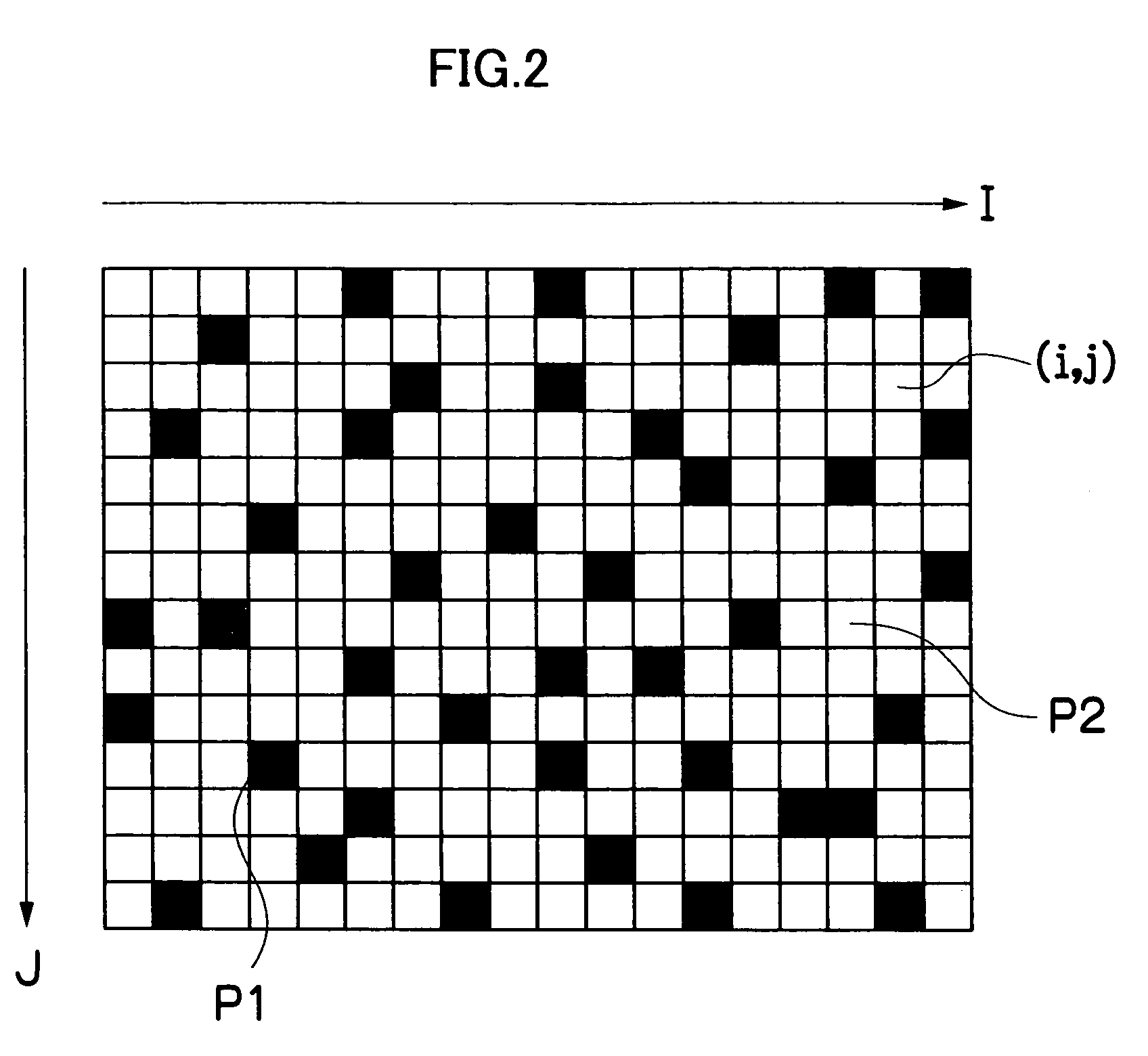
[0062] First, the basic flow of a method for determining the dot arrangement using simulated annealing (SA) will be described.

[0063] Simulated annealing is an approximate solution method for combinational optimization problems, and is particularly a method that mathematically models the physical phenomenon of annealing (a method of gradually lowering the temperature from a high temperature to create a stable crystal structure). It is known that local searching, typified by the so-called hill climbing method, is sometimes tapped in a “local optimal solution,” and the true “optimal solution” cannot be reached. In this respect, simulated annealing works to select a solution in an energetically deteriorating direction by a certain probability, wherein the probability of selecting a solution in an energetically deteriorating direction increases as the temperature increases, and the probability decreases as the temperature decreases. T...


PUM


Abstract

The dot arrangement determination method for determining an arrangement pattern when m dots (where m is a natural number) are arranged in a specific pixel area, the method comprises: a setting step of variably setting an arrangement pattern in which the m dots are arranged without overlapping at pixel positions in the specific pixel area; a first image evaluation value calculating step of calculating an image evaluation value of a halftone image formed by arranging the m dots in the specific pixel area in accordance with the arrangement pattern set in the setting step; a second image evaluation value calculating step of calculating an image evaluation value of a halftone image implemented according to the arrangement pattern set in the setting step when dots cannot be formed in an arbitrary pixel row in the specific pixel area; and a dot arrangement calculating step of determining the arrangement pattern with least image quality degradation for inability to form dots in an arbitrary pixel row in the specific pixel area by approximately solving a combinational optimization problem for the arrangement pattern using calculation results of the first and second image evaluation value calculating steps.

Description

BACKGROUND OF THE INVENTION [0001] 1. Field of the Invention [0002] The present invention relates to a dot arrangement determination method and apparatus suitable for forming pseudo gradation images, a method for creating a threshold matrix, a program for implementing the functions of these methods with a computer, and an image forming apparatus that uses a threshold matrix; and particularly relates to a halftone processing technique suitable for an inkjet recording apparatus or another image forming apparatus. [0003] 2. Description of the Related Art [0004] In an inkjet recording apparatus, ink is deposited on recording paper or another such recording medium by ejecting ink droplets from the nozzles of a recording head (also referred to as a print head), and prints or images (hereinafter referred to collectively as “images”) are recorded by these dots of deposited ink, but conditions may arise in which ink cannot be ejected from the nozzles for various reasons. For example, when a ...

Claims


Application Information

Patent Timeline
Patent Type & Authority Applications(United States)
IPC IPC(8): H04N1/405
CPCH04N1/405
Inventor YAMAZAKI, YOSHIROU
Owner FUJIFILM CORP
Why Eureka
Try Eureka