Mechanical locking system for floor panels

a technology of floor panels and locking systems, which is applied in the direction of floors, building components, floors, etc., can solve the problems of negative impact of the locking system strength and inability to increase the thickness, and achieve the effect of reducing the force needed, facilitating the connection of the floor panels, and reducing the for

Active Publication Date: 2015-10-22
CERALOC INNOVATION AB
View PDF3 Cites 91 Cited by
  • Summary
  • Abstract
  • Description
  • Claims
  • Application Information

AI Technical Summary

Benefits of technology

[0022]The protruding tongue and the snap tab is preferably configured such that the initial contact, during said vertical displacement, between the protruding tongue and the snap tab is at an upper part of t

Problems solved by technology

A problem with this method is that a flexible snap tab, arranged at an edge of a first panel, must be pressed inwardly by a sharp upper edge of an adjacent edge of a second panel.
This thickness i

Method used


Image

  • Mechanical locking system for floor panels
  • Mechanical locking system for floor panels
  • Mechanical locking system for floor panels

Examples


Embodiment Construction

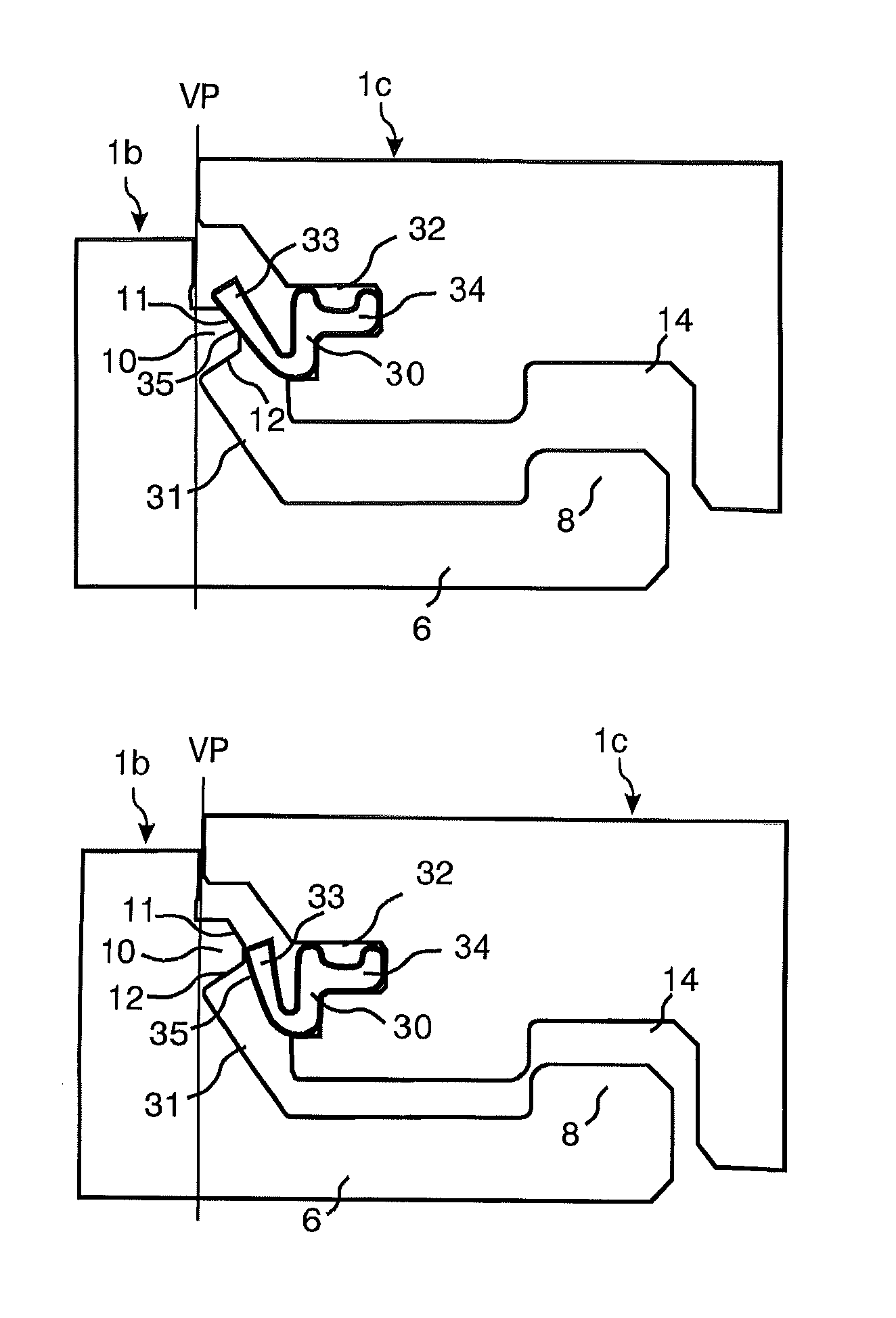
[0035]To facilitate understanding, several locking systems in the figures are shown schematically. It should be emphasized that improved or different functions may be achieved using combinations of the preferred embodiments.

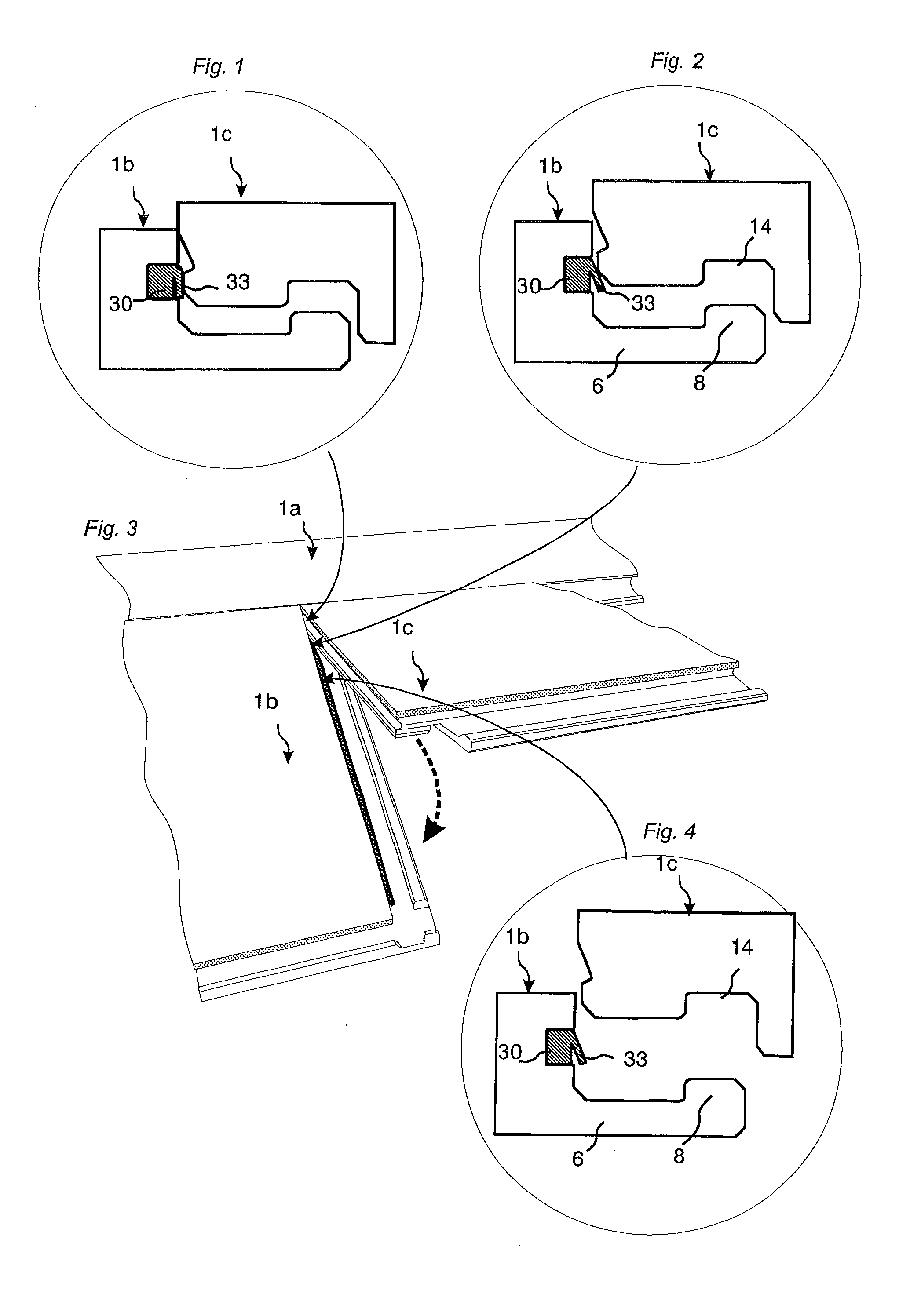
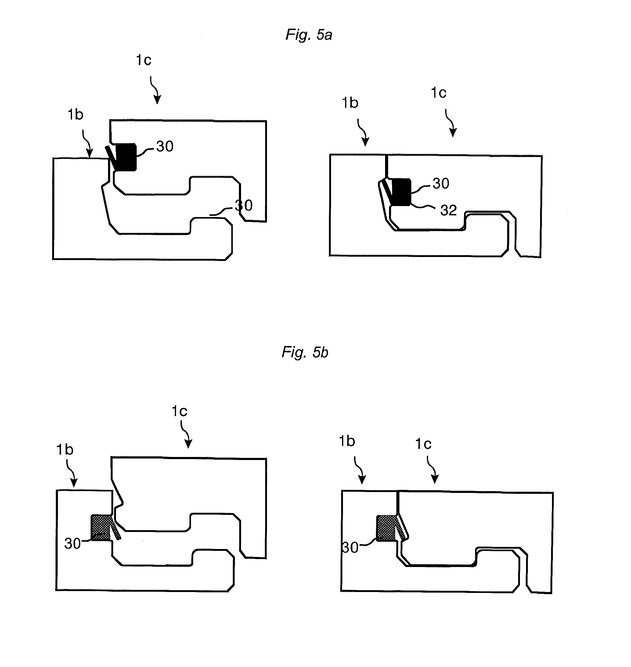
[0036]A known “fold down” installation method is described in FIGS. 1-4. Locking of short edges 1b, 1c takes place with a scissors like movement where a flexible tongue 30 is displaced inwardly gradually from one edge to the other edge when a long side of a panel 1c in one row is connected by angling to an adjacent panel 1a in a previously installed row. A flexible snap tab 33, which in most cases is made of a plastic section, is during folding bended horizontally along the joint. A part of the snap tab is during folding pressed inwardly, as shown in FIG. 1, and other parts are in contact with the adjacent edge, FIG. 2, or in an completely unlocked position, as shown in FIG. 4. The horizontal locking takes place when a locking element 8 located on a strip 6 on a ...


PUM

PropertyMeasurementUnit
Flexibilityaaaaaaaaaa

Abstract

Floor panels provided with a mechanical locking system comprising a separate material in order to reduce snapping resistance during vertical displacement. For example, a separate flexible tongue, the flexible tongue including an inner part, which is connected to a holding groove at a second edge, and an outer flexible snap tab that extends upwardly and in the connected state into a cavity under a protruding tongue for locking a first and a second floor panel to each other in a vertical direction.

Description

TECHNICAL FIELD[0001]The invention generally relates to the field of mechanical locking systems for floor panels and building panels especially floor panels with mechanical locking systems, which may be locked by a vertical displacement.FIELD OF APPLICATION OF THE INVENTION[0002]Embodiments of the present invention are particularly suitable for use in floating floors, which are formed of floor panels which are joined mechanically with a locking system integrated with the floor panel, i.e. mounted at the factory, that are made up of one or more upper layers of veneer, decorative laminate, powder based surfaces or decorative plastic material, an intermediate core of wood fibre based material or plastic material and preferably a lower balancing layer on the rear side of the core. The following description of known technique, problems of known systems and objects and features of the invention will therefore, as a non restrictive example, be aimed at this field of application and in part...

Claims


Application Information

Patent Timeline
IPC IPC(8): E04F15/02E04B5/02
CPCE04B5/02E04F15/02038E04F2201/0146E04F2201/0552E04F2201/0535E04F2201/0588
Inventor PERVAN, DARKO
Owner CERALOC INNOVATION AB
Why Eureka
Try Eureka