Method and Tool for Adjusting Cable Grips

a technology of cable grips and tools, applied in the field of cable grips, can solve the problems of reducing the length of the grip by applying compressive force, and achieve the effect of increasing the bore siz

Inactive Publication Date: 2015-10-22
ALDY WILLIAM
View PDF0 Cites 0 Cited by
  • Summary
  • Abstract
  • Description
  • Claims
  • Application Information

AI Technical Summary

Benefits of technology

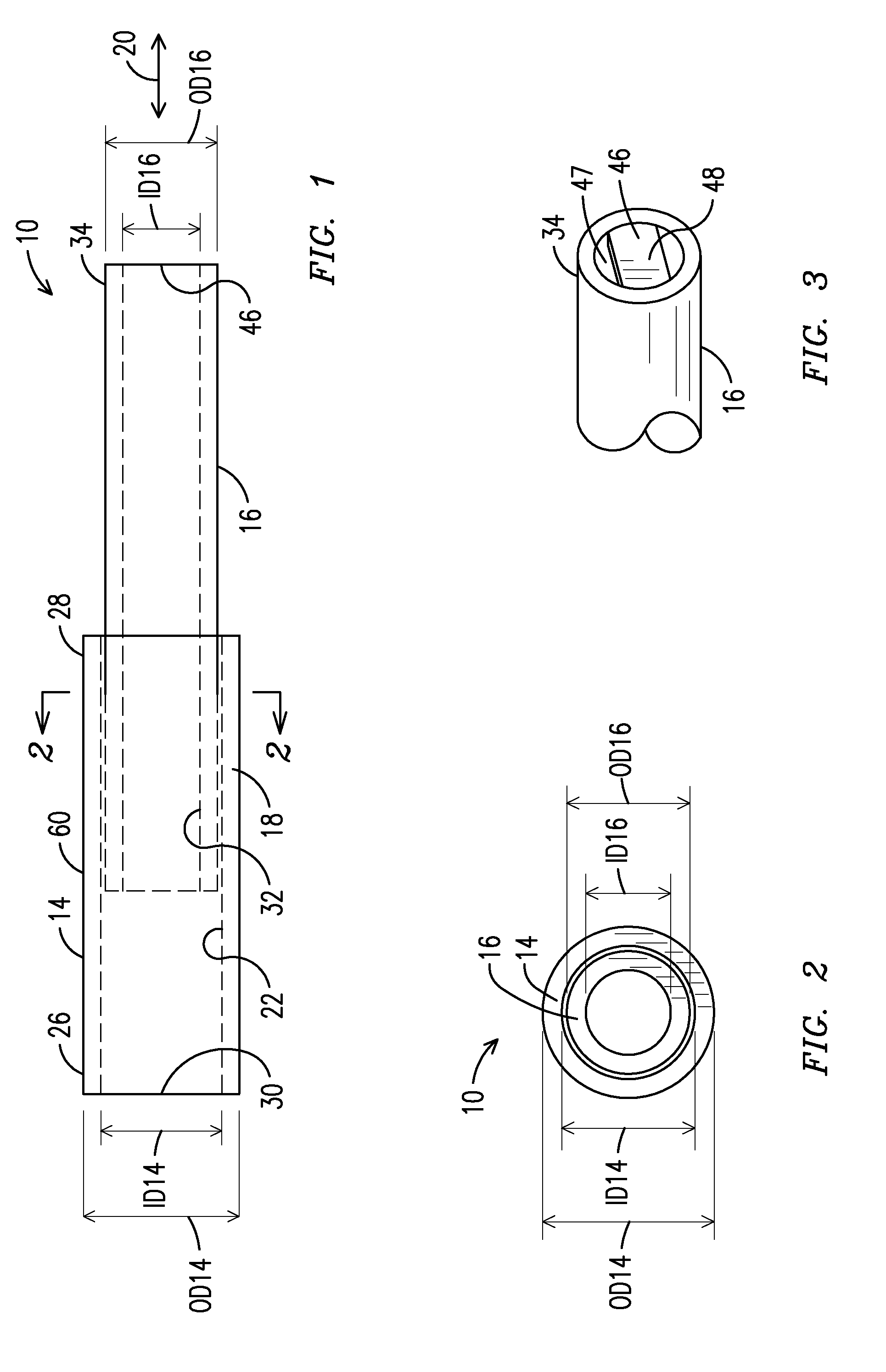
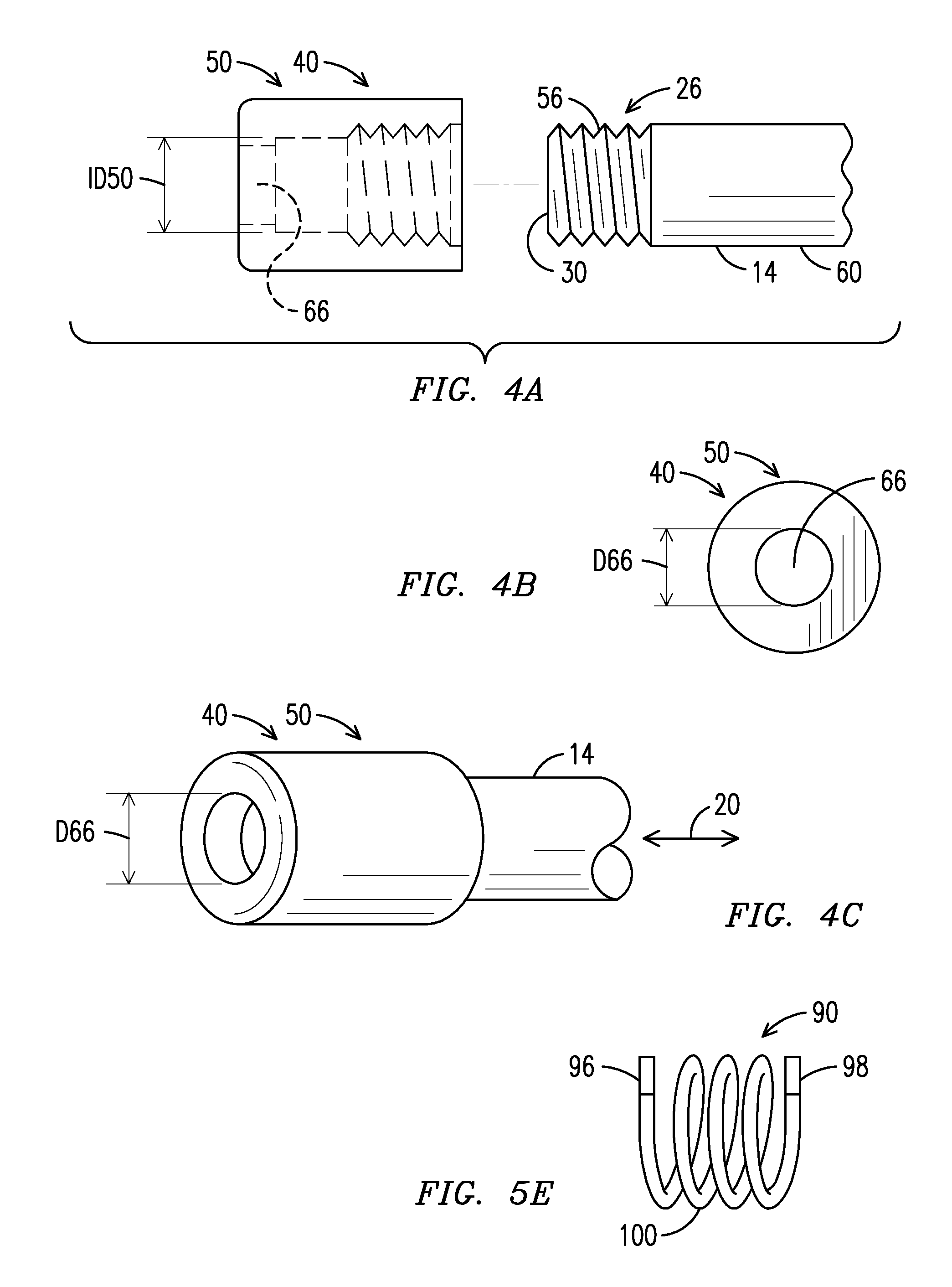
[0005]According to one embodiment of the invention a tool is provided for adjusting a grip to secure a cable within a bore in the grip surrounded by interlaced wiring. The grip is of the type which is extendable in length along a longitudinal direction so that, as the length of the grip is extended or contracted, the size of the bore is adjusted to a relatively large size in a radial direction to receive the cable or to a relatively small size in a radial direction to position the wiring against the cable. The grip has a characteristic external size in the radial direction when the bore is the relatively large size. The tool includes first and second tubular sections for containing the grip while receiving the cable into the bore, with each section having first and second ends. The second section is sized for positioning within the first section in a telescopic arrangement so that the sections provide an assembly extendable in length along a longitudinal axis. The first section has an interior dimension, in a radial direction transverse to the longitudinal axis, at least as large as the characteristic external size of the grip. The first section includes a first stop providing an opening that permits introducing the cable through the first end and into the first tubular section while the grip is contained in the tool so that movement of the grip out of the first tubular section through the first end is blocked. The second tubular section includes a second stop positioned in the second tubular section. With the grip positioned in the first and second tubular sections and between the first and second stops, when the second tubular section is displaced along the longitudinal axis and toward the first stop, a force is transferred against the grip, causing the size of the bore to increase.

Problems solved by technology

This displacing results in application of the compressive force to reduce the length of the grip.

Method used


Image

  • Method and Tool for Adjusting Cable Grips
  • Method and Tool for Adjusting Cable Grips
  • Method and Tool for Adjusting Cable Grips

Examples


Embodiment Construction

[0036]FIG. 7A illustrates a generic grip 2 exemplary of the type used to pull cable, including electrical wire, such as the segment of cable 4 shown in FIGS. 8A and 8B. Grips of this type may be referred to as a multi-weave style. They are available from numerous providers including Brenco, Inc. of Harrison Ohio USA. In the view of FIG. 7A the grip 2 is positioned to extend longitudinally along a straight axis A. The grip has at a first end an integrally formed eye loop 3 into which a hook may be placed to pull the grip when the cable is attached to the grip. As more fully described herein, the portion of the grip extending from the eye loop to the opposing end is tubular. The exemplary segment of cable 4 is a straight length as shown in FIG. 8A which extends longitudinally along the straight axis A for insertion into the grip 2. The segment of cable has a substantially circular profile in cross section with radius R as indicated in FIG. 8B. As is well known, grips of this type comp...


PUM

PropertyMeasurementUnit
sizesaaaaaaaaaa
diameteraaaaaaaaaa
diameteraaaaaaaaaa

Abstract

A tool for adjusting a grip. The tool includes a tubular section for containing the grip while receiving a cable. A first stop is positioned in or near a first end of the tubular section to provide an opening for introducing the cable into the tubular section while the grip is contained in the tool. One of first and second stops is arranged for displacement along the longitudinal axis with respect to the other stop. With the grip positioned between the first and second stops, when one of the stops is displaced toward the other stop a force is applied against the grip, causing the size of the bore to increase and the length of the grip to be contracted.

Description

FIELD OF THE INVENTION[0001]This invention relates generally to cable grips of the type adapted to be expanded and contracted radially by endwise compression and extension and, more specifically, to methods and equipment for operating such grips. This application claims priority to and is a Divisional of U.S. application Ser. No. 13 / 176,116 filed Jul. 5, 2011, which is a Continuation of Ser. No. 12 / 581,313 filed Oct. 19, 2009, now U.S. Pat. No. 7,997,843 issued Aug. 16, 2011, and incorporated herein by reference in its entirety.BACKGROUND[0002]Cable grips are used extensively in many industries to pull cable segments through conduit, along and between overhead towers, or in structural applications. Such grips are important tools for installation of both electrical and mechanical cables in, for example, bridge structures, hoisting and conveyor cables. Contemporary designs of cable grips were advanced during the first half of the twentieth century by Edgar Kellems, as described in par...

Claims


Application Information

Patent Timeline
Patent Type & Authority Applications(United States)
IPC IPC(8): F16G11/02H02G1/00
CPCH02G1/00F16G11/02Y10T29/49801
Inventor ALDY, WILLIAM
Owner ALDY WILLIAM
Why Eureka
Try Eureka